Product Description
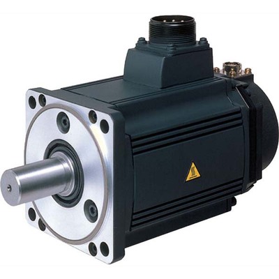
LK100Product features
No carbon brush and spark
l Large speed adjustment range
l High efficiency and large torque
l Low starting current and noise
l Small size and light weight
l High reliability double hall outgoing mode
| Product parameters | ||||||||
| model | 71 | 80 | 90 | 100 | 112 | 132 | 160 | |
| voltage range (V/DC) |
12–540 | 12–540 | 12–540 | 24–540 | 24–540 | 48–540 | 110–540 | |
| Power range (kW) |
0.3–0.8 | 0.8–1.2 | 1.0–1.8 | 1.8–3.0 | 3.0–10.0 | 5.5–15.0 | 15.0–30.0 | |
| Speed range (RPM) |
750–3000 | |||||||
| maximum efficiency | 92% (brushless DC motor), 95% (permanent magnet synchronous motor) | |||||||
| Installation method | Foot (B5), vertical (B14), foot/vertical (B34), double shaft (D2) | |||||||
| turn around | Face the outlet end, turn counterclockwise to turn CHINAMFG (the direction can be changed) | |||||||
| Motor overspeed | The motor runs continuously with a load of 50% of the rated current at 1.5 times the rated voltage | |||||||
| overload capacity | 1.5 times the rated torque for 3 minutes, the motor performance does not change, the controller cuts off the output and displays the overload protection | |||||||
| Operating temperature | -25ºC–60ºC | |||||||
| Use humidity | 20%–90%RH | |||||||
| Keep warm and humid Spend |
-30ºC–80ºC,10%–95%RH | |||||||
| Protection class | IP54 (default), other protection levels can be achieved according to customer requirements | |||||||
| Features | 1. Small size and light weight; 2. High efficiency, large torque, energy saving and environmental protection; 3. No carbon brush, no spark; 4. Small starting current and low noise; (permanent magnet synchronous motor has lower working noise than brushless DC motor) 5. Double Hall outlet with anti-static protection, high reliability; 6. The applicable voltage range is wide and the limitation is small. |
|||||||
| Customizable electricity machine |
Permanent magnet synchronous motor, self-starting permanent magnet synchronous motor, integrated motor, etc. | |||||||
Matters needing attention
l All connecting screws shall be fastened to avoid irreversible damage to the product due to poor contact
l Connect the motor phase line in strict accordance with the terminal definition, otherwise the motor will not rotate normally or cannot rotate
l The power supply voltage shall not exceed 1.2 times of the rated voltage
l It is prohibited to use it continuously under overload condition, which may cause irreversible damage to the product
/* March 10, 2571 17:59:20 */!function(){function s(e,r){var a,o={};try{e&&e.split(“,”).forEach(function(e,t){e&&(a=e.match(/(.*?):(.*)$/))&&1
| Application: | Universal, Industrial, Household Appliances, Car, Power Tools |
|---|---|
| Operating Speed: | Adjust Speed |
| Function: | Driving |
.shipping-cost-tm .tm-status-off{background: none;padding:0;color: #1470cc}
|
Shipping Cost:
Estimated freight per unit. |
about shipping cost and estimated delivery time. |
|---|
| Payment Method: |
|
|---|---|
|
Initial Payment Full Payment |
| Currency: | US$ |
|---|
| Return&refunds: | You can apply for a refund up to 30 days after receipt of the products. |
|---|

Are there innovations or emerging technologies in the field of gear motor design?
Yes, there are several innovations and emerging technologies in the field of gear motor design. These advancements aim to improve the performance, efficiency, compactness, and reliability of gear motors. Here are some notable innovations and emerging technologies in gear motor design:
1. Miniaturization and Compact Design:
Advancements in manufacturing techniques and materials have enabled the miniaturization of gear motors without compromising their performance. Gear motors with compact designs are highly sought after in applications where space is limited, such as robotics, medical devices, and consumer electronics. Innovative approaches like micro-gear motors and integrated motor-gear units are being developed to achieve smaller form factors while maintaining high torque and efficiency.
2. High-Efficiency Gearing:
New gear designs focus on improving efficiency by reducing friction and mechanical losses. Advanced gear manufacturing techniques, such as precision machining and 3D printing, allow for the creation of intricate gear tooth profiles that optimize power transmission and minimize losses. Additionally, the use of high-performance materials, coatings, and lubricants helps reduce friction and wear, improving overall gear motor efficiency.
3. Magnetic Gearing:
Magnetic gearing is an emerging technology that replaces traditional mechanical gears with magnetic fields to transmit torque. It utilizes the interaction of permanent magnets to transfer power, eliminating the need for physical gear meshing. Magnetic gearing offers advantages such as high efficiency, low noise, compactness, and maintenance-free operation. While still being developed and refined, magnetic gearing holds promise for various applications, including gear motors.
4. Integrated Electronics and Controls:
Gear motor designs are incorporating integrated electronics and controls to enhance performance and functionality. Integrated motor drives and controllers simplify system integration, reduce wiring complexity, and allow for advanced control features. These integrated solutions offer precise speed and torque control, intelligent feedback mechanisms, and connectivity options for seamless integration into automation systems and IoT (Internet of Things) platforms.
5. Smart and Condition Monitoring Capabilities:
New gear motor designs incorporate smart features and condition monitoring capabilities to enable predictive maintenance and optimize performance. Integrated sensors and monitoring systems can detect abnormal operating conditions, track performance parameters, and provide real-time feedback for proactive maintenance and troubleshooting. This helps prevent unexpected failures, extend the lifespan of gear motors, and improve overall system reliability.
6. Energy-Efficient Motor Technologies:
Gear motor design is influenced by advancements in energy-efficient motor technologies. Brushless DC (BLDC) motors and synchronous reluctance motors (SynRM) are gaining popularity due to their higher efficiency, better power density, and improved controllability compared to traditional brushed DC and induction motors. These motor technologies, when combined with optimized gear designs, contribute to overall system energy savings and performance improvements.
These are just a few examples of the innovations and emerging technologies in gear motor design. The field is continuously evolving, driven by the need for more efficient, compact, and reliable motion control solutions in various industries. Gear motor manufacturers and researchers are actively exploring new materials, manufacturing techniques, control strategies, and system integration approaches to meet the evolving demands of modern applications.
How do gear motors compare to other types of motors in terms of power and efficiency?
Gear motors can be compared to other types of motors in terms of power output and efficiency. The choice of motor type depends on the specific application requirements, including the desired power level, efficiency, speed range, torque characteristics, and control capabilities. Here’s a detailed explanation of how gear motors compare to other types of motors in terms of power and efficiency:
1. Gear Motors:
Gear motors combine a motor with a gear mechanism to deliver increased torque output and improved control. The gear reduction enables gear motors to provide higher torque while reducing the output speed. This makes gear motors suitable for applications that require high torque, precise positioning, and controlled movements. However, the gear reduction process introduces mechanical losses, which can slightly reduce the overall efficiency of the system compared to direct-drive motors. The efficiency of gear motors can vary depending on factors such as gear quality, lubrication, and maintenance.
2. Direct-Drive Motors:
Direct-drive motors, also known as gearless or integrated motors, do not use a gear mechanism. They provide a direct connection between the motor and the load, eliminating the need for gear reduction. Direct-drive motors offer advantages such as high efficiency, low maintenance, and compact design. Since there are no gears involved, direct-drive motors experience fewer mechanical losses and can achieve higher overall efficiency compared to gear motors. However, direct-drive motors may have limitations in terms of torque output and speed range, and they may require more complex control systems to achieve precise positioning.
3. Stepper Motors:
Stepper motors are a type of gear motor that excels in precise positioning applications. They operate by converting electrical pulses into incremental steps of movement. Stepper motors offer excellent positional accuracy and control. They are capable of precise positioning and can hold a position without power. Stepper motors have relatively high torque at low speeds, making them suitable for applications that require precise control and positioning, such as robotics, 3D printers, and CNC machines. However, stepper motors may have lower overall efficiency compared to direct-drive motors due to the additional power required to overcome the detents between steps.
4. Servo Motors:
Servo motors are another type of gear motor known for their high torque, high speed, and excellent positional accuracy. Servo motors combine a motor, a feedback device (such as an encoder), and a closed-loop control system. They offer precise control over position, speed, and torque. Servo motors are widely used in applications that require accurate and responsive positioning, such as industrial automation, robotics, and camera pan-tilt systems. Servo motors can achieve high efficiency when properly optimized and controlled but may have slightly lower efficiency compared to direct-drive motors due to the additional complexity of the control system.
5. Efficiency Considerations:
When comparing power and efficiency among different motor types, it’s important to consider the specific requirements and operating conditions of the application. Factors such as load characteristics, speed range, duty cycle, and control requirements influence the overall efficiency of the motor system. While direct-drive motors generally offer higher efficiency due to the absence of mechanical losses from gears, gear motors can deliver higher torque output and enhanced control capabilities. The efficiency of gear motors can be optimized through proper gear selection, lubrication, and maintenance practices.
In summary, gear motors offer increased torque and improved control compared to direct-drive motors. However, gear reduction introduces mechanical losses that can slightly impact the overall efficiency of the system. Direct-drive motors, on the other hand, provide high efficiency and compact design but may have limitations in terms of torque and speed range. Stepper motors and servo motors, both types of gear motors, excel in precise positioning applications but may have slightly lower efficiency compared to direct-drive motors. The selection of the most suitable motor type depends on the specific requirements of the application, balancing power, efficiency, speed range, and control capabilities.

Can you explain the advantages of using gear motors in various mechanical systems?
Gear motors offer several advantages when utilized in various mechanical systems. Their unique characteristics make them well-suited for applications that require controlled power transmission, precise speed control, and torque amplification. Here’s a detailed explanation of the advantages of using gear motors:
1. Torque Amplification:
One of the key advantages of gear motors is their ability to amplify torque. By using different gear ratios, gear motors can increase or decrease the output torque from the motor. This torque amplification is crucial in applications that require high torque output, such as lifting heavy loads or operating machinery with high resistance. Gear motors allow for efficient power transmission, enabling the system to handle demanding tasks effectively.
2. Speed Control:
Gear motors provide precise speed control, allowing for accurate and controlled movement in mechanical systems. By selecting the appropriate gear ratio, the rotational speed of the output shaft can be adjusted to match the requirements of the application. This speed control capability ensures that the mechanical system operates at the desired speed, whether it needs to be fast or slow. Gear motors are commonly used in applications such as conveyors, robotics, and automated machinery, where precise speed control is essential.
3. Directional Control:
Another advantage of gear motors is their ability to control the rotational direction of the output shaft. By using different types of gears, such as spur gears, bevel gears, or worm gears, the direction of rotation can be easily changed. This directional control is beneficial in applications that require bidirectional movement, such as in actuators, robotic arms, and conveyors. Gear motors offer reliable and efficient directional control, contributing to the versatility and functionality of mechanical systems.
4. Efficiency and Power Transmission:
Gear motors are known for their high efficiency in power transmission. The gear system helps distribute the load across multiple gears, reducing the strain on individual components and minimizing power losses. This efficient power transmission ensures that the mechanical system operates with optimal energy utilization and minimizes wasted power. Gear motors are designed to provide reliable and consistent power transmission, resulting in improved overall system efficiency.
5. Compact and Space-Saving Design:
Gear motors are compact in size and offer a space-saving solution for mechanical systems. By integrating the motor and gear system into a single unit, gear motors eliminate the need for additional components and reduce the overall footprint of the system. This compact design is especially beneficial in applications with limited space constraints, allowing for more efficient use of available space while still delivering the necessary power and functionality.
6. Durability and Reliability:
Gear motors are designed to be robust and durable, capable of withstanding demanding operating conditions. The gear system helps distribute the load, reducing the stress on individual gears and increasing overall durability. Additionally, gear motors are often constructed with high-quality materials and undergo rigorous testing to ensure reliability and longevity. This makes gear motors well-suited for continuous operation in industrial and commercial applications, where reliability is crucial.
By leveraging the advantages of torque amplification, speed control, directional control, efficiency, compact design, durability, and reliability, gear motors provide a reliable and efficient solution for various mechanical systems. They are widely used in industries such as robotics, automation, manufacturing, automotive, and many others, where precise and controlled mechanical power transmission is essential.


editor by CX 2024-02-18
China Hot selling High Torque Permanent Magnet Electric 24V 3000rpm 50W Small Volume Servo BLDC Brushless DC Gear Motor with Gearbox for Industrial Fan vacuum pump brakes
Product Description
57BLY DC Brushless Motor
Introducing the High Torque Permanent Magnet Electric 24V 3000RPM 50W Small Volume Servo BLDC Brushless DC Gear Motor with Gearbox for Industrial Fan. This universal motor operates at a constant speed and is excited by a brushless DC motor. Perfect for industrial, household appliances, cars, and power tools.
Product Description
| Projects | Specifications |
| Winding Type | Star |
| Hall Effect Angle | 120° electrical angle |
| Shaft Axial Play | 0.571mm |
| Ambient Temperature | -20~ + 50°C |
| Ambient Humidity | <80% |
| Max. Radial Force | 75N@20mm from the flange |
| Max. Axial Force | 20N |
| Insulation Class | Class B |
| Dielectric Strength | one minute@500VAC |
| Insulation Resistance | 100MΩMin.@500VDC |
Product Parameters
| Model | Rated Voltage | Rated Torque | Rated Speed | Rated Current | Rated Power | Peak Torque | Torque Constant | Body Length | Weight |
| VDC | N.M | RPM | A | W | N.M | N.M/A | MM | KG | |
| 57BLY55-230 | 24 | 0.16 | 3000 | 2.8 | 50 | 0.48 | 0.057 | 55 | 0.46 |
| 57BLY55-460 | 48 | 0.16 | 6000 | 2.8 | 100 | 0.48 | 0.057 | 55 | 0.46 |
| 57BLY75-230 | 24 | 0.32 | 3000 | 5.6 | 100 | 0.96 | 0.057 | 75 | 0.75 |
| 57BLY75-460 | 48 | 0.32 | 6000 | 5.6 | 200 | 0.96 | 0.057 | 75 | 0.75 |
| 57BLY95-230 | 24 | 0.48 | 3000 | 8.4 | 150 | 1.44 | 0.057 | 95 | 1 |
| 57BLY95-460 | 48 | 0.48 | 6000 | 8.4 | 300 | 1.44 | 0.057 | 95 | 1 |
| 57BLY115-230 | 24 | 0.64 | 3000 | 11.2 | 200 | 1.92 | 0.057 | 115 | 1.2 |
| 57BLY115-460 | 48 | 0.64 | 6000 | 11.2 | 400 | 1.92 | 0.057 | 115 | 1.2 |
Note:Brake, reducer, encoder, handwheel and other devices can be installed.
Please feel free to contact us for more details.
Detailed Photos
Application Area
Product Recommendation
| Stepper motor | Brushless motor | Synchronous motor |
Company Profile
HangZhou Sino-pan Electric Co., Ltd. is an export-oriented enterprise. Located in Xihu (West Lake) Dis. District, HangZhou City, ZheJiang Province, China. After years of operation, the scale of our enterprise has continued to expand. Gradually grow into a group company. At present, our company mainly produces automotive bulbs (such as halogen bulbs and automotive LED bulbs/as well as household LEDs and commercial LEDs), motors (brushless motors/stepping motors/synchronous motors/asynchronous motors). At the same time, we are also appointed by many clients as purchasing and quality inspection agents in China.
We provide you with high-quality, fast, efficient and inexpensive automotive lighting, motors and auxiliary electrical services. Zhongpan welcomes your patronage with a sHangZhou, and we will provide you with a variety of satisfactory products and a full range of consulting services. We firmly believe that the cooperation with us will be infinitely better! Strive to create a stronger tomorrow for our customers!
Packaging & Shipping
FAQ
Q1. Can I provide sample orders for your products?
A: Of course, you can check our quality before ordering. If you have any requirements, please contact us.
Q2. What is your delivery time?
A: It depends on the order quantity. Usually, it takes about 3-7 days after receiving the small deposit. Bulk ordering takes 10-20 days.
Q3. What kind of customers and what kind of companies do you work with?
A: We have 20 years of export experience and serve more than 100 customers, such as retailers, wholesalers, and online store owners.
Q4. Is it possible to put our logo on your product or product packaging?
A: Of course, we have a factory, welcome to customize your brand, LOGO, color, product manual, packaging, etc.
Q5: Can you OEM for me?
A: We accept all OEM orders, just contact us and give me your design. We will provide you with a reasonable price and make samples for you as soon as possible.
Q6: What are your payment terms?
A: According to T/T, LC AT SIGHT, 30% deposit in advance, and the balance 70% before shipment.
/* March 10, 2571 17:59:20 */!function(){function s(e,r){var a,o={};try{e&&e.split(“,”).forEach(function(e,t){e&&(a=e.match(/(.*?):(.*)$/))&&1
| Application: | Universal, Industrial, Household Appliances, Car, Power Tools |
|---|---|
| Operating Speed: | Constant Speed |
| Excitation Mode: | Excited |
| Customization: |
Available
|
|
|---|
.shipping-cost-tm .tm-status-off{background: none;padding:0;color: #1470cc}
|
Shipping Cost:
Estimated freight per unit. |
about shipping cost and estimated delivery time. |
|---|
| Payment Method: |
|
|---|---|
|
Initial Payment Full Payment |
| Currency: | US$ |
|---|
| Return&refunds: | You can apply for a refund up to 30 days after receipt of the products. |
|---|
What role does the controller play in the overall performance of a servo motor?
The controller plays a crucial role in the overall performance of a servo motor system. It is responsible for monitoring and regulating the motor’s operation to achieve the desired motion and maintain system stability. Let’s explore in detail the role of the controller in the performance of a servo motor:
1. Motion Control:
The controller is responsible for generating precise control signals that dictate the motor’s speed, torque, and position. It receives input commands from the user or higher-level control system and translates them into appropriate control signals for the servo motor. By accurately controlling the motor’s motion, the controller enables precise positioning, smooth acceleration and deceleration, and the ability to follow complex trajectories. The controller’s effectiveness in generating accurate and responsive control signals directly impacts the motor’s motion control capabilities.
2. Feedback Control:
The controller utilizes feedback from position sensors, such as encoders, to monitor the motor’s actual position, speed, and other parameters. It compares the desired motion profile with the actual motor behavior and continuously adjusts the control signals to minimize any deviations or errors. This closed-loop feedback control mechanism allows the controller to compensate for disturbances, variations in load conditions, and other factors that may affect the motor’s performance. By continuously monitoring and adjusting the control signals based on feedback, the controller helps maintain accurate and stable motor operation.
3. PID Control:
Many servo motor controllers employ Proportional-Integral-Derivative (PID) control algorithms to regulate the motor’s behavior. PID control calculates control signals based on the error between the desired setpoint and the actual motor response. The proportional term responds to the present error, the integral term accounts for accumulated past errors, and the derivative term considers the rate of change of the error. By tuning the PID parameters, the controller can achieve optimal performance in terms of response time, stability, and steady-state accuracy. Properly configured and tuned PID control greatly influences the servo motor’s ability to follow commands accurately and efficiently.
4. Trajectory Planning:
In applications requiring complex motion profiles or trajectories, the controller plays a vital role in trajectory planning. It determines the optimal path and speed profile for the motor to follow, taking into account constraints such as acceleration limits, jerk limits, and mechanical limitations. The controller generates the required control signals to achieve the desired trajectory, ensuring smooth and precise motion. Effective trajectory planning by the controller enhances the motor’s performance in applications that involve intricate or high-speed movements.
5. System Monitoring and Protection:
The controller monitors various parameters of the servo motor system, including temperature, current, voltage, and other diagnostic information. It incorporates protective measures to prevent damage or excessive stress on the motor. The controller can implement safety features such as overcurrent protection, over-temperature protection, and fault detection mechanisms. By actively monitoring and safeguarding the motor and the system, the controller helps prevent failures, prolongs the motor’s lifespan, and ensures safe and reliable operation.
6. Communication and Integration:
The controller facilitates communication and integration with other components or systems within the overall automation setup. It may support various communication protocols, such as Ethernet, CAN bus, or fieldbus protocols, enabling seamless integration with higher-level control systems, human-machine interfaces (HMIs), or other peripheral devices. The controller’s ability to efficiently exchange data and commands with other system components allows for coordinated and synchronized operation, enhancing the overall performance and functionality of the servo motor system.
In summary, the controller plays a vital role in the overall performance of a servo motor system. It enables precise motion control, utilizes feedback for closed-loop control, implements PID control algorithms, plans complex trajectories, monitors system parameters, and facilitates communication and integration. The controller’s capabilities and effectiveness directly impact the motor’s performance in terms of accuracy, responsiveness, stability, and overall system efficiency.
How is the size of a servo motor determined based on application requirements?
The size of a servo motor is an important consideration when selecting a motor for a specific application. The size of the motor is determined based on various factors related to the application requirements. Let’s explore how the size of a servo motor is determined:
1. Torque Requirements:
One of the primary factors in determining the size of a servo motor is the torque requirements of the application. The motor should be able to generate sufficient torque to handle the load and overcome any resistance or friction in the system. The required torque depends on factors such as the weight of the load, the distance from the motor’s axis of rotation, and any additional forces acting on the system. By analyzing the torque requirements, one can select a servo motor with an appropriate size and torque rating to meet the application’s needs.
2. Speed and Acceleration Requirements:
The desired speed and acceleration capabilities of the application also influence the size of the servo motor. Different applications have varying speed and acceleration requirements, and the motor needs to be capable of achieving the desired performance. Higher speeds and accelerations may require larger motors with more powerful components to handle the increased forces and stresses. By considering the required speed and acceleration, one can determine the size of the motor that can meet these demands.
3. Inertia and Load Inertia Ratio:
The inertia of the load and the inertia ratio between the load and the servo motor are important considerations in sizing the motor. Inertia refers to the resistance of an object to changes in its rotational motion. If the load has a high inertia, it requires a servo motor with sufficient size and torque to accelerate and decelerate the load effectively. The inertia ratio, which is the ratio of the load inertia to the motor inertia, affects the motor’s ability to control the load’s motion accurately. A proper balance between the load and motor inertia is necessary to achieve optimal performance and stability in the system.
4. Duty Cycle and Continuous Operation:
The duty cycle and continuous operation requirements of the application also impact the motor size selection. Duty cycle refers to the ratio of the motor’s operating time to the total cycle time. Applications with high-duty cycles or continuous operation may require larger motors that can handle sustained operation without overheating or performance degradation. It is important to consider the motor’s continuous torque rating and thermal characteristics to ensure it can operate reliably under the given duty cycle requirements.
5. Physical Space Constraints:
The physical space available for installing the servo motor is another factor to consider. The motor’s dimensions should fit within the available space, considering factors such as motor length, diameter, and any mounting requirements. It is essential to ensure that the chosen motor can be easily integrated into the system without interfering with other components or causing space constraints.
6. Weight Limitations:
The weight limitations of the application may influence the motor size selection. If there are weight restrictions, such as in mobile or lightweight applications, it is necessary to choose a servo motor that is compact and lightweight while still providing the required performance. Lighter servo motors can help optimize the overall weight and balance of the system.
7. Cost Considerations:
Cost is also a factor to consider when determining the size of a servo motor. Larger motors with higher torque and performance capabilities tend to be more expensive. It is important to strike a balance between the required performance and the cost constraints of the application. Analyzing the cost-effectiveness and overall value of the motor in relation to the application requirements is essential.
By considering these factors, one can determine the appropriate size of a servo motor that can meet the specific application requirements. It is advisable to consult with manufacturers or experts in the field to ensure the chosen motor size aligns with the application needs and provides optimal performance and reliability.
Can you explain the difference between a servo motor and a regular electric motor?
A servo motor and a regular electric motor are both types of electric motors, but they have distinct differences in terms of design, control, and functionality.
A regular electric motor, also known as an induction motor or a DC motor, is designed to convert electrical energy into mechanical energy. It consists of a rotor, which rotates, and a stator, which surrounds the rotor and generates a rotating magnetic field. The rotor is connected to an output shaft, and when current flows through the motor’s windings, it creates a magnetic field that interacts with the stator’s magnetic field, resulting in rotational motion.
On the other hand, a servo motor is a more specialized type of electric motor that incorporates additional components for precise control of position, speed, and acceleration. It consists of a regular electric motor, a sensor or encoder, and a feedback control system. The sensor or encoder provides feedback on the motor’s current position, and this information is used by the control system to adjust the motor’s behavior.
The key difference between a servo motor and a regular electric motor lies in their control mechanisms. A regular electric motor typically operates at a fixed speed based on the voltage and frequency of the power supply. In contrast, a servo motor can be controlled to rotate to a specific angle or position and maintain that position accurately. The control system continuously monitors the motor’s actual position through the feedback sensor and adjusts the motor’s operation to achieve the desired position or follow a specific trajectory.
Another distinction is the torque output of the motors. Regular electric motors generally provide high torque at low speeds and lower torque at higher speeds. In contrast, servo motors are designed to deliver high torque at both low and high speeds, which makes them suitable for applications that require precise and dynamic motion control.
Furthermore, servo motors often have a more compact and lightweight design compared to regular electric motors. They are commonly used in applications where precise positioning, speed control, and responsiveness are critical, such as robotics, CNC machines, automation systems, and remote-controlled vehicles.
In summary, while both servo motors and regular electric motors are used to convert electrical energy into mechanical energy, servo motors offer enhanced control capabilities, precise positioning, and high torque at various speeds, making them well-suited for applications that require accurate and dynamic motion control.
editor by CX 2024-02-17
China best Three Phase Asynchronous AC Induction Electric Gear Reducer Fan Blower Vacuum Air Compressor Water Pump Universal Industry Machine Motor vacuum pump ac system
Product Description
Product Description
Introduction:
Y2 series three-phase asynchronous motor is Y series motor the upgrading of product, is the totally enclosed, fan-cooled induction motor for general purpose .
It was the newest product in the 90S’ ,its overall level has reached the same products abroad at the beginning of 90S’level. The product apply to economic lake-off fields, such as machine tools, water pump, fan, compressor, also can be applied to transportation, stirring, printing, agricultural machinery, food and other kinds of excluding inflammable, explosive or corrosive gas.
Y2 series three phase asynchronous motor installation size and power grade in conformity with relevant standards of IEC and Germany DIN42673 standard line and Y series motor, its shell protection grade for IP54, cooling method for IC41l, operate continuously (S1). Using F insulation class and grade B assessment according to temperature (except for 315 L2-2, 4355 all specifications F grade the assessment, and ask the assessment load noise index.
Y2 series three-phase asynchronous motor the rated voltage is 380 V. rated frequency is 50 Hz. 3 KW the following connection is Y , other power are delta connection . Motor running the place at no more than 1000 m; Environment air temperature changes with seasons, but no more than 40 °C; Minimum environment air temperature is-15 °C; The wet month average high relative humidity is 90%; At the same time, this month is not higher than the lowest average temperature 25 °C.
Motor Features:
1. Frame size:H56-355;
2. Power:0.12-315Kw;
3. Voltage: 380V;
4. Rated Frequency: 50 Hz / 60 Hz;
5. Poles: 2 / 4 / 6 / 8 / 10
6. Speed: 590 -2980 r/min
7. Ambient Temperature: -15°C-40°C
8. Model of CONEECTION: Y-Connection for 3 KW motor or less while Delta-Connection for 4 KW motor or more;
9. Mounting: B3; B5; B35; B14; B34;
10. Current: 1.5-465 A (AC);
11. Duty: continuous (S1);
12. Insulation Class: B;
13. Protection Class: IP44,IP54,IP55;
14. Frame material: aluminum body(56-132 frame), cast iron(71-355 frame)
15. Terminal box : Top or Side
16. Cooling Method: IC411 Standards;
17. Altitude: No more than 1,000 meters above sea level;
18. Packing: 63-112 frame be packaged by carton&pallets
132-355 frame be packaged by plywood case;
19. Certifications: CE, CCC, ISO9001: 2008
Factory Advantages
1 . 15 years history
2. Competitive Price
3. Guaranteed Quality
4. Fast delivery time, Normal models about 15-20days , another not normal models need about 30days
5. 100% testing after each process and final testing before packing ,all raw material is good quality .100% cooper wire, Cold-rolled silicon steel sheet,good quaility shafts ,bearings,stators ,fan,fan covers.and so on.
6. High efficiency
7. Low noise
8. Long life
9. Power saving
10. Slight vibration
11. It is newly designed in conformity with the relevant rules of IEC standards, Strictly and Perfect Management is guaranteed for Production ;
12. Professional Service
13. Warranty: 12 months from date of delivery
14. Main Market: South America, Middle East, Southest Asia, Europe,Africa and so on
15. We have Certification for CE, CCC, ISO9001,High quality and competitive price !
Installation Instructions
| Y2 Three-phase Asynchronous Electric Motor | |
| 1). Power: | 0.12KW-315KW; |
| 2). Frame: | H56 to 355; |
| 3). Shell: | cast iron body , aluminum body ; |
| 4). Pole: | 2/4/6/8 poles; |
| 5). Mounting arrangement: | B3/B5/B14/B35/B34 or other; |
| 6). Voltage: | 220V, 380V, 400V, 415V, 440V or on request (50Hz or 60Hz); |
| 7). Protection class: | IP54 / IP55 /IP65; |
| 8). Duty/Rating: | S1 (Continuous); |
| 9). Cooling method: | IC411 (SELF-FAN cooling); |
| 10). Insulation class: | F; |
| 11).Standard: | (IEC) EN60034-1 & EN1065714-1. |
Technical Data
| TYPE | OUTPUT | FULL LOAD | Ist/TN | Tst/TN | Tmax/TN | |||||
| HP | KW | Speed (RPM) |
Current (A) |
Efficiency η(%) |
Power Factor (cosΦ) |
|||||
| Synchronous Speed 3000 rpm | ||||||||||
| Y2-631-2 | 0.18 | 0.25 | 2720 | 0.53 | 65 | 0.80 | 5.5 | 2.2 | 2.2 | |
| Y2-632-2 | 0.25 | 0.34 | 2720 | 0.69 | 68 | 0.81 | 5.5 | 2.2 | 2.2 | |
| Y2-711-2 | 0.37 | 0.5 | 2740 | 0.99 | 70 | 0.81 | 6.1 | 2.2 | 2.2 | |
| Y2-712-2 | 0.55 | 0.75 | 2740 | 1.4 | 73 | 0.82 | 6.1 | 2.2 | 2.3 | |
| Y2-801-2 | 0.75 | 1 | 2835 | 1.83 | 77.4 | 0.83 | 6.1 | 2.2 | 2.3 | |
| Y2-802-2 | 1.1 | 1.5 | 2835 | 2.58 | 79.6 | 0.84 | 7 | 2.2 | .2.3 | |
| Y2-90S-2 | 1.5 | 2 | 2845 | 3.43 | 81.3 | 0.84 | 7 | 2.2 | 2.3 | |
| Y2-90L-2 | 2.2 | 3 | 2845 | 4.85 | 83.2 | 0.85 | 7 | 2.2 | 2.3 | |
| Y2-100L-2 | 3 | 4 | 2875 | 6.31 | 84.6 | 0.87 | 7.5 | 2.2 | 2.3 | |
| Y2-112M-2 | 4 | 5.5 | 2895 | 8.1 | 85.8 | 0.88 | 7.5 | 2.2 | 2.3 | |
| Y2-132S1-2 | 5.5 | 7.5 | 2905 | 11 | 87 | 0.88 | 7.5 | 2.2 | 2.3 | |
| Y2-132S2-2 | 7.5 | 10 | 2905 | 14.9 | 88.1 | 0.88 | 7.5 | 2.2 | 2.3 | |
| Y2-160M1-2 | 11 | 15 | 2935 | 21.3 | 89.4 | 0.89 | 7.5 | 2.2 | 2.3 | |
| Y2-160M2-2 | 15 | 20 | 2935 | 28.8 | 90.3 | 0.89 | 7.5 | 2.2 | 2.3 | |
| Y2-160L-2 | 18.5 | 25 | 2935 | 34.7 | 90.9 | 0.90 | 7.5 | 2.2 | 2.3 | |
| Y2-180M-2 | 22 | 30 | 2945 | 41 | 91.3 | 0.90 | 7.5 | 2 | 2.3 | |
| Y2-200L1-2 | 30 | 40 | 2955 | 55.5 | 92 | 0.90 | 7.5 | 2 | 2.3 | |
| Y2-200L2-2 | 37 | 50 | 2955 | 67.9 | 92.5 | 0.90 | 7.5 | 2 | 2.3 | |
| Y2-225M-2 | 45 | 60 | 2975 | 82.3 | 92.9 | 0.92 | 7.5 | 2 | 2.3 | |
| Y2-250M-2 | 55 | 75 | 2975 | 101 | 93.2 | 0.90 | 7.5 | 2 | 2.3 | |
| Y2-280S-2 | 75 | 100 | 2975 | 134 | 93.8 | 0.90 | 7.5 | 2 | 2.3 | |
| Y2-315S-2 | 110 | 150 | 2980 | 195 | 94.3 | 0.91 | 7.1 | 1.8 | 2.2 | |
| Y2-315M-2 | 132 | 180 | 2980 | 233 | 94.6 | 0.91 | 7.1 | 1.8 | 2.2 | |
| Y2-315L1-2 | 160 | 200 | 2980 | 279 | 94.8 | 0.92 | 7.1 | 1.8 | 2.2 | |
| Y2-315L2-2 | 200 | 270 | 2980 | 348 | 95 | 0.92 | 7.1 | 1.8 | 2.2 | |
| Y2-355M-2 | 250 | 340 | 2980 | 433 | 95 | 0.92 | 7.1 | 1.6 | 2.2 | |
| Y2-355L-2 | 315 | 430 | 2980 | 544 | 95 | 0.92 | 5.8 | 1.6 | 2.2 | |
| Y2-400M1-2 | 355 | 475 | 2975 | 618 | 95.9 | 0.91 | 5.8 | 1.23 | 2.53 | |
| Y2-400M2-2 | 400 | 535 | 2982 | 689 | 96.0 | 0.92 | 5.74 | 1.31 | 2.43 | |
| Y2-400M3-2 | 450 | 600 | 2982 | 775 | 96.1 | 0.92 | 7.27 | 1.83 | 2.98 | |
| Y2-400L1-2 | 500 | 670 | 2982 | 853 | 96.3 | 0.92 | 6.14 | 1.2 | 2.9 | |
| Y2-400L2-2 | 560 | 750 | 2982 | 952 | 96.3 | 0.92 | 5.46 | 0.98 | 2.57 | |
| Synchronous Speed 1500 rpm | ||||||||||
| Y2-631-4 | 0.12 | 0.17 | 1310 | 0.44 | 57 | 0.72 | 4.4 | 2.1 | 2.2 | |
| Y2-632-4 | 0.18 | 0.25 | 1310 | 1.62 | 60 | 0.73 | 4.4 | 2.1 | 2.2 | |
| Y2-711-4 | 0.25 | 0.34 | 1330 | 0.79 | 65 | 0.75 | 5.2 | 2.1 | 2.2 | |
| Y2-712-4 | 0.37 | 0.5 | 1330 | 1.12 | 67 | 0.74 | 5.2 | 2.1 | 2.2 | |
| Y2-801-4 | 0.55 | 0.75 | 1395 | 1.57 | 71 | 0.75 | 5.2 | 2.4 | 2.3 | |
| Y2-802-4 | 0.75 | 1 | 1395 | 2.03 | 79.6 | 0.76 | 6 | 2.3 | 2.3 | |
| Y2-90S-4 | 1.1 | 1.5 | 1405 | 2.89 | 81.4 | 0.77 | 6 | 2.3 | 2.3 | |
| Y2-90L-4 | 1.5 | 2 | 1405 | 3.7 | 82.8 | 0.79 | 6 | 2.3 | 2.3 | |
| Y2-100L1-4 | 2.2 | 3 | 1435 | 5.16 | 84.3 | 0.81 | 7 | 2.3 | 2.3 | |
| Y2-100L2-4 | 3 | 4 | 1435 | 6.78 | 85.5 | 0.82 | 7 | 2.3 | 2.3 | |
| Y2-112M-4 | 4 | 5.5 | 1445 | 8.8 | 86.6 | 0.82 | 7 | 2.3 | 2.3 | |
| Y2-132S-4 | 5.5 | 7.5 | 1445 | 11.7 | 87.7 | 0.83 | 7 | 2.3 | 2.3 | |
| Y2-132M-4 | 7.5 | 10 | 1445 | 15.6 | 88.7 | 0.84 | 7 | 2.3 | 2.3 | |
| Y2-160M-4 | 11 | 15 | 1460 | 22.3 | 89.8 | 0.84 | 7 | 2.2 | 2.3 | |
| Y2-160L-4 | 15 | 20 | 1460 | 30.1 | 90.6 | 0.85 | 7.5 | 2.2 | 2.3 | |
| Y2-180M-4 | 18.5 | 25 | 1470 | 36.5 | 91.2 | 0.86 | 7.5 | 2.2 | 2.3 | |
| Y2-180L-4 | 22 | 30 | 1470 | 43.2 | 91.6 | 0.86 | 7.5 | 2.2 | 2.3 | |
| Y2-200L-4 | 30 | 40 | 1470 | 57.6 | 92.3 | 0.86 | 7.2 | 2.2 | 2.3 | |
| Y2-225S-4 | 37 | 50 | 1485 | 69.9 | 92.7 | 0.87 | 7.2 | 2.2 | 2.3 | |
| Y2-225M-4 | 45 | 60 | 1485 | 84.7 | 93.1 | 0.87 | 7.2 | 2.2 | 2.3 | |
| Y2-250M-4 | 55 | 75 | 1485 | 103 | 93.5 | 0.87 | 7.2 | 2.2 | 2.3 | |
| Y2-280S-4 | 75 | 100 | 1485 | 140 | 94 | 0.87 | 7.2 | 2.2 | 2.3 | |
| Y2-280M-4 | 90 | 125 | 1490 | 167 | 94.2 | 0.87 | 7.2 | 2.2 | 2.3 | |
| Y2-315S-4 | 110 | 150 | 1490 | 201 | 94.5 | 0.88 | 6.9 | 2.1 | 2.2 | |
| Y2-315M-4 | 132 | 180 | 1490 | 240 | 94.7 | 0.88 | 6.9 | 2.1 | 2.2 | |
| Y2-315L1-4 | 160 | 200 | 1490 | 287 | 94.9 | 0.89 | 6.9 | 2.1 | 2.2 | |
| Y2-315L2-4 | 200 | 270 | 1490 | 359 | 94.1 | 0.89 | 6.9 | 2.1 | 2.2 | |
| Y2-355M-4 | 250 | 340 | 1485 | 443 | 95.1 | 0.90 | 6.9 | 2.1 | 2.2 | |
| Y2-355L-4 | 315 | 430 | 1485 | 556 | 95.1 | 0.90 | 6.9 | 2.1 | 2.2 | |
| Y2-400M1-4 | 355 | 475 | 1490 | 641 | 95.5 | 0.88 | 6.5 | 2.6 | 1.93 | |
| Y2-400M2-4 | 400 | 535 | 1490 | 723 | 95.5 | 0.88 | 6.5 | 2.75 | 1.8 | |
| Y2-400M3-4 | 450 | 600 | 1490 | 804 | 95.5 | 0.89 | 6.5 | 2.81 | 2.03 | |
| Y2-400L1-4 | 500 | 670 | 1490 | 893 | 95.6 | 0.89 | 6.61 | 2.52 | 1.83 | |
| Y2-400L2-4 | 560 | 750 | 1490 | 971 | 96.0 | 0.89 | 6.6 | 2.67 | 2.02 | |
| Synchronous Speed 1000 rpm | ||||||||||
| Y2-711-6 | 0.18 | 0.25 | 850 | 0.74 | 56 | 0.66 | 4 | 1.9 | 2 | |
| Y2-712-6 | 0.25 | 0.34 | 850 | 0.95 | 59 | 0.68 | 4 | 1.9 | 2 | |
| Y2-801-6 | 0.37 | 0.5 | 890 | 1.3 | 62 | 0.70 | 4.7 | 1.9 | 2 | |
| Y2-802-6 | 0.55 | 0.75 | 890 | 1.79 | 65 | 0.72 | 4.7 | 1.9 | 2.1 | |
| Y2-90S-6 | 0.7 | 1 | 915 | 2.29 | 75.9 | 0.72 | 5.5 | 2 | 2.1 | |
| Y2-90L-6 | 1.1 | 1.5 | 915 | 3.18 | 78.1 | 0.73 | 5.5 | 2 | 2.1 | |
| Y2-100L-6 | 1.5 | 2 | 945 | 3.94 | 79.8 | 0.75 | 5.5 | 2 | 2.1 | |
| Y2-112M-6 | 2.2 | 3 | 945 | 5.6 | 81.8 | 0.76 | 6.5 | 2 | 2.1 | |
| Y2-132S-6 | 3 | 4 | 965 | 7.4 | 83.3 | 0.76 | 6.5 | 2.1 | 2.1 | |
| Y2-132M1-6 | 4 | 5.5 | 965 | 9.8 | 84.6 | 0.76 | 6.5 | 2.1 | 2.1 | |
| Y2-132M2-6 | 5.5 | 7.5 | 965 | 12.9 | 86 | 0.77 | 6.5 | 2.1 | 2.1 | |
| Y2-160M-6 | 7.5 | 10 | 975 | 17 | 87.2 | 0.78 | 6.5 | 2 | 2.1 | |
| Y2-160L-6 | 11 | 15 | 975 | 24.2 | 88.7 | 0.81 | 7 | 2 | 2.1 | |
| Y2-180L-6 | 15 | 20 | 975 | 31.6 | 89.7 | 0.81 | 7 | 2 | 2.1 | |
| Y2-200L1-6 | 18.5 | 25 | 975 | 38.6 | 90.4 | 0.83 | 7 | 2.1 | 2.1 | |
| Y2-200L2-6 | 22 | 30 | 975 | 44.7 | 90.9 | 0.84 | 7 | 2.1 | 2.1 | |
| Y2-225M-6 | 30 | 40 | 980 | 59.3 | 91.7 | 0.86 | 7 | 2 | 2.1 | |
| Y2-250M-6 | 37 | 50 | 980 | 71 | 92.2 | 0.86 | 7 | 2.1 | 2.1 | |
| Y2-280S-6 | 45 | 60 | 980 | 86 | 92.7 | 0.86 | 7 | 2.1 | 2 | |
| Y2-280M-6 | 55 | 75 | 980 | 105 | 93.1 | 0.86 | 7 | 2.1 | 2 | |
| Y2-315S-6 | 75 | 100 | 980 | 141 | 93.7 | 0.86 | 7 | 2 | 2 | |
| Y2-315M-6 | 90 | 125 | 980 | 169 | 94 | 0.86 | 7 | 2 | 2 | |
| Y2-315L1-6 | 110 | 150 | 980 | 206 | 94.3 | 0.86 | 6.7 | 2 | 2 | |
| Y2-315L2-6 | 132 | 180 | 980 | 244 | 94.6 | 0.87 | 6.7 | 2 | 2 | |
| Y2-355M1-6 | 160 | 200 | 985 | 292 | 94.8 | 0.88 | 6.7 | 1.9 | 2 | |
| Y2-355M2-6 | 200 | 270 | 985 | 365 | 95 | 0.88 | 6.7 | 1.9 | 2 | |
| Y2-355L-6 | 250 | 340 | 985 | 455 | 95 | 0.88 | 6.7 | 1.9 | 2 | |
| Y2-400M1-6 | 280 | 380 | 990 | 510 | 95.8 | 0.87 | 5.9 | 2.3 | 1.8 | |
| Y2-400M2-6 | 315 | 430 | 990 | 574 | 95.8 | 0.87 | 5.9 | 2.3 | 1.8 | |
| Y2-400M3-6 | 355 | 475 | 990 | 638 | 95.8 | 0.87 | 5.9 | 2.3 | 1.8 | |
| Y2-400L1-6 | 400 | 535 | 990 | 719 | 96.0 | 0.88 | 6.3 | 2.3 | 1.8 | |
| Y2-400L2-6 | 450 | 600 | 990 | 796 | 96.5 | 0.89 | 6.3 | 2.3 | 1.8 | |
| Synchronous Speed 750 rpm | ||||||||||
| Y2-801-8 | 0.18 | 0.25 | 630 | 0.88 | 51 | 0.61 | 3.3 | 1.8 | 1.9 | |
| Y2-802-8 | 0.25 | 0.34 | 640 | 1.15 | 54 | 0.61 | 3.3 | 1.8 | 1.9 | |
| Y2-90S-8 | 0.37 | 0.5 | 660 | 1.49 | 62 | 0.61 | 4 | 1.8 | 1.9 | |
| Y2-90L-8 | 0.55 | 0.75 | 660 | 2.18 | 63 | 0.61 | 4 | 1.8 | 2 | |
| Y2-100L1-8 | 0.75 | 1 | 680 | 2.39 | 71 | 0.67 | 4 | 1.8 | 2 | |
| Y2-100L2-8 | 1.1 | 1.5 | 680 | 3.32 | 73 | 0.69 | 5 | 1.8 | 2 | |
| Y2-112M-8 | 1.5 | 2 | 690 | 4.5 | 75 | 0.69 | 5 | 1.8 | 2 | |
| Y2-132S-8 | 2.2 | 3 | 690 | 6 | 78 | 0.71 | 6 | 1.8 | 2 | |
| Y2-132M-8 | 3 | 4 | 710 | 7.9 | 79 | 0.73 | 6 | 1.8 | 2 | |
| Y2-160M1-8 | 4 | 5 | 710 | 10.3 | 81 | 0.73 | 6 | 1.9 | 2 | |
| Y2-160M2-8 | 5.5 | 7.5 | 720 | 13.6 | 83 | 0.74 | 6 | 2 | 2 | |
| Y2-160L-8 | 7.5 | 10 | 720 | 17.8 | 85.5 | 0.75 | 6 | 2 | 2 | |
| Y2-180L-8 | 11 | 15 | 730 | 25.1 | 87.5 | 0.76 | 6.6 | 2 | 2 | |
| Y2-200L-8 | 15 | 20 | 730 | 34.1 | 88 | 0.76 | 6.6 | 2 | 2 | |
| Y2-225S-8 | 18.5 | 25 | 730 | 40.6 | 90 | 0.76 | 6.6 | 1.9 | 2 | |
| Y2-225M-8 | 22 | 30 | 740 | 47.4 | 90.5 | 0.78 | 6.6 | 1.9 | 2 | |
| Y2-250M-8 | 30 | 40 | 740 | 64 | 91 | 0.79 | 6.6 | 1.9 | 2 | |
| Y2-280S-8 | 37 | 50 | 740 | 78 | 91.5 | 0.79 | 6.6 | 1.9 | 2 | |
| Y2-280M-8 | 45 | 60 | 740 | 94 | 92 | 0.79 | 6.6 | 1.9 | 2 | |
| Y2-315S-8 | 55 | 75 | 740 | 111 | 92.8 | 0.81 | 6.6 | 1.8 | 2 | |
| Y2-315M-8 | 75 | 100 | 740 | 151 | 93 | 0.81 | 6.6 | 1.8 | 2 | |
| Y2-315L1-8 | 90 | 125 | 740 | 178 | 93.8 | 0.82 | 6.6 | 1.8 | 2 | |
| Y2-315L2-8 | 110 | 150 | 740 | 217 | 94 | 0.82 | 7.2 | 1.8 | 2 | |
| Y2-355M1-8 | 132 | 180 | 740 | 261 | 93.7 | 0.82 | 7.2 | 1.8 | 2 | |
| Y2-355M2-8 | 160 | 200 | 740 | 315 | 94.2 | 0.82 | 7.2 | 1.8 | 2 | |
| Y2-355L-8 | 200 | 270 | 740 | 388 | 94.5 | 0.83 | 7.2 | 1.8 | 2 | |
| Y2-400M1-8 | 250 | 340 | 745 | 494 | 95.0 | 0.81 | 6.2 | 2.3 | 1.8 | |
| Y2-400M2-8 | 280 | 380 | 745 | 552 | 95.0 | 0.82 | 6.2 | 2.3 | 1.8 | |
| Y2-400L1-8 | 315 | 430 | 745 | 592 | 95.0 | 0.85 | 6.2 | 2.3 | 1.8 | |
| Y2-400L2-8 | 355 | 475 | 745 | 692 | 95.0 | 0.85 | 6.2 | 2.3 | 1.8 | |
| Y2-400L3-8 | 400 | 535 | 745 | 780 | 95.0 | 0.85 | 6.2 | 2.3 | 1.8 | |
| Synchronous Speed 600 rpm | ||||||||||
| Y2-315S-10 | 45 | 60 | 590 | 100 | 91.5 | 0.75 | 6.2 | 1.5 | 2 | |
| Y2-315M-10 | 55 | 75 | 590 | 121 | 92 | 0.75 | 6.2 | 1.5 | 2 | |
| Y2-315L1-10 | 75 | 100 | 590 | 162 | 92.5 | 0.76 | 6.2 | 1.2 | 2 | |
| Y2-315L2-10 | 90 | 125 | 590 | 191 | 93 | 0.77 | 6.2 | 1.5 | 2 | |
| Y2-355M1-10 | 110 | 150 | 590 | 230 | 93.2 | 0.78 | 6 | 1.3 | 2 | |
| Y2-355M2-10 | 132 | 180 | 590 | 275 | 93.5 | 0.78 | 6 | 1.3 | 2 | |
| Y2-355L-10 | 160 | 200 | 590 | 334 | 93.5 | 0.78 | 6 | 1.3 | 2 | |
| Y2-400M1-10 | 200 | 270 | 595 | 404 | 95.0 | 0.80 | 6.2 | 2.6 | 1.8 | |
| Y2-400M2-10 | 250 | 340 | 595 | 495 | 95.0 | 0.81 | 6.2 | 2.6 | 1.8 | |
| Y2-400L1-10 | 280 | 380 | 595 | 554 | 95.0 | 0.82 | 6.2 | 2.6 | 1.8 | |
| Y2-400L2-10 | 315 | 430 | 595 | 630 | 95.0 | 0.82 | 6.2 | 2.6 | 1.8 | |
Detailed Photos
Our OEM Motors, Diesel generator sets ,Alternators are talior made to fit the OEM customer’s application. Our based Engineering Design team work with you to ensure the motor meets your individual needs.
2 ,4,6 ,8 and 10 pole operation. with CE Approvals available
All Motors, Diesel generator sets ,Alternators may be designed for optional voltages and frequencies.
/* March 10, 2571 17:59:20 */!function(){function s(e,r){var a,o={};try{e&&e.split(“,”).forEach(function(e,t){e&&(a=e.match(/(.*?):(.*)$/))&&1
| Application: | Industrial |
|---|---|
| Speed: | Variable Speed |
| Number of Stator: | Three-Phase |
| Customization: |
Available
|
|
|---|
.shipping-cost-tm .tm-status-off{background: none;padding:0;color: #1470cc}
|
Shipping Cost:
Estimated freight per unit. |
about shipping cost and estimated delivery time. |
|---|
| Payment Method: |
|
|---|---|
|
Initial Payment Full Payment |
| Currency: | US$ |
|---|
| Return&refunds: | You can apply for a refund up to 30 days after receipt of the products. |
|---|
Are there innovations or emerging technologies in the field of gear motor design?
Yes, there are several innovations and emerging technologies in the field of gear motor design. These advancements aim to improve the performance, efficiency, compactness, and reliability of gear motors. Here are some notable innovations and emerging technologies in gear motor design:
1. Miniaturization and Compact Design:
Advancements in manufacturing techniques and materials have enabled the miniaturization of gear motors without compromising their performance. Gear motors with compact designs are highly sought after in applications where space is limited, such as robotics, medical devices, and consumer electronics. Innovative approaches like micro-gear motors and integrated motor-gear units are being developed to achieve smaller form factors while maintaining high torque and efficiency.
2. High-Efficiency Gearing:
New gear designs focus on improving efficiency by reducing friction and mechanical losses. Advanced gear manufacturing techniques, such as precision machining and 3D printing, allow for the creation of intricate gear tooth profiles that optimize power transmission and minimize losses. Additionally, the use of high-performance materials, coatings, and lubricants helps reduce friction and wear, improving overall gear motor efficiency.
3. Magnetic Gearing:
Magnetic gearing is an emerging technology that replaces traditional mechanical gears with magnetic fields to transmit torque. It utilizes the interaction of permanent magnets to transfer power, eliminating the need for physical gear meshing. Magnetic gearing offers advantages such as high efficiency, low noise, compactness, and maintenance-free operation. While still being developed and refined, magnetic gearing holds promise for various applications, including gear motors.
4. Integrated Electronics and Controls:
Gear motor designs are incorporating integrated electronics and controls to enhance performance and functionality. Integrated motor drives and controllers simplify system integration, reduce wiring complexity, and allow for advanced control features. These integrated solutions offer precise speed and torque control, intelligent feedback mechanisms, and connectivity options for seamless integration into automation systems and IoT (Internet of Things) platforms.
5. Smart and Condition Monitoring Capabilities:
New gear motor designs incorporate smart features and condition monitoring capabilities to enable predictive maintenance and optimize performance. Integrated sensors and monitoring systems can detect abnormal operating conditions, track performance parameters, and provide real-time feedback for proactive maintenance and troubleshooting. This helps prevent unexpected failures, extend the lifespan of gear motors, and improve overall system reliability.
6. Energy-Efficient Motor Technologies:
Gear motor design is influenced by advancements in energy-efficient motor technologies. Brushless DC (BLDC) motors and synchronous reluctance motors (SynRM) are gaining popularity due to their higher efficiency, better power density, and improved controllability compared to traditional brushed DC and induction motors. These motor technologies, when combined with optimized gear designs, contribute to overall system energy savings and performance improvements.
These are just a few examples of the innovations and emerging technologies in gear motor design. The field is continuously evolving, driven by the need for more efficient, compact, and reliable motion control solutions in various industries. Gear motor manufacturers and researchers are actively exploring new materials, manufacturing techniques, control strategies, and system integration approaches to meet the evolving demands of modern applications.

Can gear motors be used for precise positioning, and if so, what features enable this?
Yes, gear motors can be used for precise positioning in various applications. The combination of gear mechanisms and motor control features enables gear motors to achieve accurate and repeatable positioning. Here’s a detailed explanation of the features that enable gear motors to be used for precise positioning:
1. Gear Reduction:
One of the key features of gear motors is their ability to provide gear reduction. Gear reduction refers to the process of reducing the output speed of the motor while increasing the torque. By using the appropriate gear ratio, gear motors can achieve finer control over the rotational movement, allowing for more precise positioning. The gear reduction mechanism enables the motor to rotate at a slower speed while maintaining higher torque, resulting in improved accuracy and control.
2. High Resolution Encoders:
Many gear motors are equipped with high-resolution encoders. An encoder is a device that measures the position and speed of the motor shaft. High-resolution encoders provide precise feedback on the motor’s rotational position, allowing for accurate position control. The encoder signals are used in conjunction with motor control algorithms to ensure precise positioning by monitoring and adjusting the motor’s movement in real-time. The use of high-resolution encoders greatly enhances the gear motor’s ability to achieve precise and repeatable positioning.
3. Closed-Loop Control:
Gear motors with closed-loop control systems offer enhanced positioning capabilities. Closed-loop control involves continuously comparing the actual motor position (as measured by the encoder) with the desired position and making adjustments to minimize any position error. The closed-loop control system uses feedback from the encoder to adjust the motor’s speed, direction, and torque, ensuring accurate positioning even in the presence of external disturbances or variations in the load. Closed-loop control enables gear motors to actively correct for position errors and maintain precise positioning over time.
4. Stepper Motors:
Stepper motors are a type of gear motor that provides excellent precision and control for positioning applications. Stepper motors operate by converting electrical pulses into incremental steps of movement. Each step corresponds to a specific angular displacement, allowing precise positioning control. Stepper motors offer high step resolution, allowing for fine position adjustments. They are commonly used in applications that require precise positioning, such as robotics, 3D printers, and CNC machines.
5. Servo Motors:
Servo motors are another type of gear motor that excels in precise positioning tasks. Servo motors combine a motor, a feedback device (such as an encoder), and a closed-loop control system. They offer high torque, high speed, and excellent positional accuracy. Servo motors are capable of dynamically adjusting their speed and torque to maintain the desired position accurately. They are widely used in applications that require precise and responsive positioning, such as industrial automation, robotics, and camera pan-tilt systems.
6. Motion Control Algorithms:
Advanced motion control algorithms play a crucial role in enabling gear motors to achieve precise positioning. These algorithms, implemented in motor control systems or dedicated motion controllers, optimize the motor’s behavior to ensure accurate positioning. They take into account factors such as acceleration, deceleration, velocity profiling, and jerk control to achieve smooth and precise movements. Motion control algorithms enhance the gear motor’s ability to start, stop, and position accurately, reducing position errors and overshoot.
By leveraging gear reduction, high-resolution encoders, closed-loop control, stepper motors, servo motors, and motion control algorithms, gear motors can be effectively used for precise positioning in various applications. These features enable gear motors to achieve accurate and repeatable positioning, making them suitable for tasks that require precise control and reliable positioning performance.

How does the gearing mechanism in a gear motor contribute to torque and speed control?
The gearing mechanism in a gear motor plays a crucial role in controlling torque and speed. By utilizing different gear ratios and configurations, the gearing mechanism allows for precise manipulation of these parameters. Here’s a detailed explanation of how the gearing mechanism contributes to torque and speed control in a gear motor:
The gearing mechanism consists of multiple gears with varying sizes, tooth configurations, and arrangements. Each gear in the system engages with another gear, creating a mechanical connection. When the motor rotates, it drives the rotation of the first gear, which then transfers the motion to subsequent gears, ultimately resulting in the output shaft’s rotation.
Torque Control:
The gearing mechanism in a gear motor enables torque control through the principle of mechanical advantage. The gear system utilizes gears with different numbers of teeth, known as gear ratio, to adjust the torque output. When a smaller gear (pinion) engages with a larger gear (gear), the pinion rotates faster than the gear but exerts more force or torque. This results in torque amplification, allowing the gear motor to deliver higher torque at the output shaft while reducing the rotational speed. Conversely, if a larger gear engages with a smaller gear, torque reduction occurs, resulting in higher rotational speed at the output shaft.
By selecting the appropriate gear ratio, the gearing mechanism effectively adjusts the torque output of the gear motor to match the requirements of the application. This torque control capability is essential in applications that demand high torque for heavy lifting or overcoming resistance, as well as applications that require lower torque but higher rotational speed.
Speed Control:
The gearing mechanism also contributes to speed control in a gear motor. The gear ratio determines the relationship between the rotational speed of the input shaft (driven by the motor) and the output shaft. When a gear motor has a higher gear ratio (more teeth on the driven gear compared to the driving gear), it reduces the output speed while increasing the torque. Conversely, a lower gear ratio increases the output speed while reducing the torque.
By choosing the appropriate gear ratio, the gearing mechanism allows for precise speed control in a gear motor. This is particularly useful in applications that require specific speed ranges or variations, such as conveyor systems, robotic movements, or machinery that needs to operate at different speeds for different tasks. The speed control capability of the gearing mechanism enables the gear motor to match the desired speed requirements of the application accurately.
In summary, the gearing mechanism in a gear motor contributes to torque and speed control by utilizing different gear ratios and configurations. It enables torque amplification or reduction, depending on the gear arrangement, allowing the gear motor to deliver the required torque output. Additionally, the gear ratio also determines the relationship between the rotational speed of the input and output shafts, providing precise speed control. These torque and speed control capabilities make gear motors versatile and suitable for a wide range of applications in various industries.
editor by CX 2024-02-11
China high quality 16 Inch Stand Fan Electric Cooling Fan Motor 100V AC With Frequency 50Hz – 60Hz and 1 Year Warranty with Great quality
Warranty: 3months-1year, 12 Months
Model Number: VNSC4-CVC01700
Type: Electric Fan Motor
Frequency: 60Hz
Phase: Single-phase
Protect Feature: Totally Enclosed
AC Voltage: 100V
Efficiency: IE 1
Product Name: VNSC4-CVC01700
Material: Copper wire
Size: 16 Inch
Speed: 3 speeds
Voltage: 100V
Power: 54W
Usage: Stand fan, Wall fan
Brand: Cuong Vinh
Package: 18 pcs
Packaging Details: 18pcs/ctn
Port: CAT LAI PORT/ Ho Chi Minh
Banner Specification
| Warranty | 3months-1year |
| Place of Origin | Vietnam |
| Brand Name | Cuong Vinh |
| Type | Electric Fan Motor |
| Frequency | 60Hz |
| Phase | Single-phase |
| Certification | RoHS, UL, VDE |
| Protect Feature | Totally Enclosed |
| AC Voltage | 100V |
| Efficiency | IE 1 |
| Product Name | VNSC4-CVC01700 |
| Material | Copper wire |
| Size | 16 Inch |
The Benefits of Using a Gear Motor
A gear motor works on the principle of conservation of angular momentum. As the smaller gear covers more RPM and the larger gear produces more torque, the ratio between the two is greater than one. Similarly, a multiple gear motor follows the principle of energy conservation, with the direction of rotation always opposite to the one that is adjacent to it. It’s easy to understand the concept behind gear motors and the various types available. Read on to learn about the different types of gears and their applications.
Electric motor
The choice of an electric motor for gear motor is largely dependent on the application. There are various motor and gearhead combinations available, and some are more efficient than others. However, it is critical to understand the application requirements and select a motor that meets these needs. In this article, we’ll examine some of the benefits of using a gear motor. The pros and cons of each type are briefly discussed. You can buy new gear motors at competitive prices, but they aren’t the most reliable or durable option for your application.
To determine which motor is best for your application, you’ll need to consider the load and speed requirements. A gear motor’s efficiency (e) can be calculated by taking the input and output values and calculating their relation. On the graph below, the input (T) and output (P) values are represented as dashed lines. The input (I) value is represented as the torque applied to the motor shaft. The output (P) is the amount of mechanical energy converted. A DC gear motor is 70% efficient at 3.75 lb-in / 2,100 rpm.
In addition to the worm gear motor, you can also choose a compact DC worm gear motor with a variable gear ratio from 7.5 to 80. It has a range of options and can be custom-made for your specific application. The 3-phase AC gear motor, on the other hand, works at a rated power of one hp and torque of 1.143.2 kg-m. The output voltage is typically 220V.
Another important factor is the output shaft orientation. There are two main orientations for gearmotors: in-line and offset. In-line output shafts are most ideal for applications with high torque and short reduction ratios. If you want to avoid backlash, choose a right angle output shaft. An offset shaft can cause the output shaft to become excessively hot. If the output shaft is angled at a certain angle, it may be too large or too small.
Gear reducer
A gear reducer is a special kind of speed reducing motor, usually used in large machinery, such as compressors. These reducers have no cooling fan and are not designed to handle heavy loads. Different purposes require different service factors. For instance, a machine that requires frequent fast accelerations and occasional load spikes needs a gear reducer with a high service factor. A gear reducer that’s designed for long production shifts should be larger than a machine that uses it for short periods of time.
A gear reducer can reduce the speed of a motor by a factor of two. The reduction ratio changes the rotation speed of the receiving member. This change in speed is often required to solve problems of inertia mismatch. The torque density of a gear reducer is measured in newton meters and will depend on the motor used. The first criterion is the configuration of the input and output shafts. A gear ratio of 2:1, for example, means that the output speed has been cut in half.
Bevel gear reducers are a good option if the input and output shafts are perpendicular. This type is very robust and is perfect for situations where the angle between two axes is small. However, bevel gear reducers are expensive and require constant maintenance. They are usually used in heavy-duty conveyors and farm equipment. The correct choice of gear reducer for gear motor is crucial for the efficiency and reliability of the mechanism. To get the best gear reducer for your application, talk to a qualified manufacturer today.
Choosing a gear reducer for a gear motor can be tricky. The wrong one can ruin an entire machine, so it’s important to know the specifics. You must know the torque and speed requirements and choose a motor with the appropriate ratio. A gear reducer should also be compatible with the motor it’s intended for. In some cases, a smaller motor with a gear reducer will work better than a larger one.
Motor shaft
Proper alignment of the motor shaft can greatly improve the performance and life span of rotating devices. The proper alignment of motors and driven instruments enhances the transfer of energy from the motor to the instrument. Incorrect alignment leads to additional noise and vibration. It may also lead to premature failure of couplings and bearings. Misalignment also results in increased shaft and coupling temperatures. Hence, proper alignment is critical to improve the efficiency of the driven instrument.
When choosing the correct type of gear train for your motor, you need to consider its energy efficiency and the torque it can handle. A helical geared motor is more efficient for high output torque applications. Depending on the required speed and torque, you can choose between an in-line and a parallel helical geared motor. Both types of gears have their advantages and disadvantages. Spur gears are widespread. They are toothed and run parallel to the motor shaft.
A planetary gear motor can also have a linear output shaft. A stepping motor should not operate at too high current to prevent demagnetization, which will lead to step loss or torque drop. Ensure that the motor and gearbox output shafts are protected from external impacts. If the motor and gearbox are not protected against bumps, they may cause thread defects. Make sure that the motor shafts and rotors are protected from external impacts.
When choosing a metal for your gear motor’s motor shaft, you should consider the cost of hot-rolled bar stock. Its outer layers are more difficult to machine. This type of material contains residual stresses and other problems that make it difficult to machine. For these applications, you should choose a high-strength steel with hard outer layers. This type of steel is cheaper, but it also has size considerations. It’s best to test each material first to determine which one suits your needs.
In addition to reducing the speed of your device, a geared motor also minimizes the torque generated by your machine. It can be used with both AC and DC power. A high-quality gear motor is vital for stirring mechanisms and conveyor belts. However, you should choose a geared motor that uses high-grade gears and provides maximum efficiency. There are many types of planetary gear motors and gears on the market, and it’s important to choose the right one.
First stage gears
The first stage gears of a gear motor are the most important components of the entire device. The motor’s power transmission is 90% efficient, but there are many factors that can affect its performance. The gear ratios used should be high enough to handle the load, but not too high that they are limiting the motor’s speed. A gear motor should also have a healthy safety factor, and the lubricant must be sufficient to overcome any of these factors.
The transmission torque of the gear changes with its speed. The transmission torque at the input side of the gear decreases, transferring a small torque to the output side. The number of teeth and the pitch circle diameters can be used to calculate the torque. The first stage gears of gear motors can be categorized as spur gears, helical gears, or worm gears. These three types of gears have different torque capacities.
The first stage helical gear is the most important part of a gear motor. Its function is to transfer rotation from one gear to the other. Its output is the gearhead. The second stage gears are connected by a carrier. They work in tandem with the first stage gear to provide the output of the gearhead. Moreover, the first stage carrier rotates in the same direction as the input pinion.
Another important component is the output torque of the gearmotor. When choosing a gearmotor, consider the starting torque, running torque, output speed, overhung and shock loads, duty cycles, and more. It is crucial to choose a gearmotor with the right ratio for the application. By choosing the proper gearmotor, you will get maximum performance with minimal operating costs and increase plant productivity. For more information on first stage gears, check out our blog.
The first stage of a gear motor is composed of a set of fixed and rotating sprockets. The first stage of these gears acts as a drive gear. Its rotational mass is a limiting factor for torque. The second stage consists of a rotating shaft. This shaft rotates in the direction of the torque axis. It is also the limiting force for the motor’s torque.
editor by czh
China Professional Bed Lifting System Dual Motor Electric Linear Actuator Electric Bicycle CAR FAN ROHS Boat Home Appliance Ce near me manufacturer
Warranty: 3months-1year
Model Number: HJA1
Usage: BOAT, Car, Electric Bicycle, FAN, Home Appliance, Hospital bed, Home Appliance, Furniture,Hospital bed
Speed(RPM): custom
Continuous Current(A): custom
Efficiency: IE 2
Model: HJA1E
Motor type: DC Motor
Color: White/ Black
Push Force: 2*6000N
No-load Speed: 4.3mm/s
Installation distance: 581mm±2mm
Material: Plastic + Metal
OEM: Yes
Certification: ce, RoHS
Packaging Details: 12/18/20/24/30 units per box
SPECIFICATION
Model
HJA1E
Input Voltage
12/24V
Max. push Force
2×6000N
No-load Speed
4.3mm/S
Installation Dimension
581mm±2mm
Appearence Dimension
707×148×121mm
Drawing Packing & Delivery Company Profile Exhibition
The Benefits of Using a Gear Motor
A gear motor works on the principle of conservation of angular momentum. As the smaller gear covers more RPM and the larger gear produces more torque, the ratio between the two is greater than one. Similarly, a multiple gear motor follows the principle of energy conservation, with the direction of rotation always opposite to the one that is adjacent to it. It’s easy to understand the concept behind gear motors and the various types available. Read on to learn about the different types of gears and their applications.
Electric motor
The choice of an electric motor for gear motor is largely dependent on the application. There are various motor and gearhead combinations available, and some are more efficient than others. However, it is critical to understand the application requirements and select a motor that meets these needs. In this article, we’ll examine some of the benefits of using a gear motor. The pros and cons of each type are briefly discussed. You can buy new gear motors at competitive prices, but they aren’t the most reliable or durable option for your application.
To determine which motor is best for your application, you’ll need to consider the load and speed requirements. A gear motor’s efficiency (e) can be calculated by taking the input and output values and calculating their relation. On the graph below, the input (T) and output (P) values are represented as dashed lines. The input (I) value is represented as the torque applied to the motor shaft. The output (P) is the amount of mechanical energy converted. A DC gear motor is 70% efficient at 3.75 lb-in / 2,100 rpm.
In addition to the worm gear motor, you can also choose a compact DC worm gear motor with a variable gear ratio from 7.5 to 80. It has a range of options and can be custom-made for your specific application. The 3-phase AC gear motor, on the other hand, works at a rated power of one hp and torque of 1.143.2 kg-m. The output voltage is typically 220V.
Another important factor is the output shaft orientation. There are two main orientations for gearmotors: in-line and offset. In-line output shafts are most ideal for applications with high torque and short reduction ratios. If you want to avoid backlash, choose a right angle output shaft. An offset shaft can cause the output shaft to become excessively hot. If the output shaft is angled at a certain angle, it may be too large or too small.
Gear reducer
A gear reducer is a special kind of speed reducing motor, usually used in large machinery, such as compressors. These reducers have no cooling fan and are not designed to handle heavy loads. Different purposes require different service factors. For instance, a machine that requires frequent fast accelerations and occasional load spikes needs a gear reducer with a high service factor. A gear reducer that’s designed for long production shifts should be larger than a machine that uses it for short periods of time.
A gear reducer can reduce the speed of a motor by a factor of two. The reduction ratio changes the rotation speed of the receiving member. This change in speed is often required to solve problems of inertia mismatch. The torque density of a gear reducer is measured in newton meters and will depend on the motor used. The first criterion is the configuration of the input and output shafts. A gear ratio of 2:1, for example, means that the output speed has been cut in half.
Bevel gear reducers are a good option if the input and output shafts are perpendicular. This type is very robust and is perfect for situations where the angle between two axes is small. However, bevel gear reducers are expensive and require constant maintenance. They are usually used in heavy-duty conveyors and farm equipment. The correct choice of gear reducer for gear motor is crucial for the efficiency and reliability of the mechanism. To get the best gear reducer for your application, talk to a qualified manufacturer today.
Choosing a gear reducer for a gear motor can be tricky. The wrong one can ruin an entire machine, so it’s important to know the specifics. You must know the torque and speed requirements and choose a motor with the appropriate ratio. A gear reducer should also be compatible with the motor it’s intended for. In some cases, a smaller motor with a gear reducer will work better than a larger one.
Motor shaft
Proper alignment of the motor shaft can greatly improve the performance and life span of rotating devices. The proper alignment of motors and driven instruments enhances the transfer of energy from the motor to the instrument. Incorrect alignment leads to additional noise and vibration. It may also lead to premature failure of couplings and bearings. Misalignment also results in increased shaft and coupling temperatures. Hence, proper alignment is critical to improve the efficiency of the driven instrument.
When choosing the correct type of gear train for your motor, you need to consider its energy efficiency and the torque it can handle. A helical geared motor is more efficient for high output torque applications. Depending on the required speed and torque, you can choose between an in-line and a parallel helical geared motor. Both types of gears have their advantages and disadvantages. Spur gears are widespread. They are toothed and run parallel to the motor shaft.
A planetary gear motor can also have a linear output shaft. A stepping motor should not operate at too high current to prevent demagnetization, which will lead to step loss or torque drop. Ensure that the motor and gearbox output shafts are protected from external impacts. If the motor and gearbox are not protected against bumps, they may cause thread defects. Make sure that the motor shafts and rotors are protected from external impacts.
When choosing a metal for your gear motor’s motor shaft, you should consider the cost of hot-rolled bar stock. Its outer layers are more difficult to machine. This type of material contains residual stresses and other problems that make it difficult to machine. For these applications, you should choose a high-strength steel with hard outer layers. This type of steel is cheaper, but it also has size considerations. It’s best to test each material first to determine which one suits your needs.
In addition to reducing the speed of your device, a geared motor also minimizes the torque generated by your machine. It can be used with both AC and DC power. A high-quality gear motor is vital for stirring mechanisms and conveyor belts. However, you should choose a geared motor that uses high-grade gears and provides maximum efficiency. There are many types of planetary gear motors and gears on the market, and it’s important to choose the right one.
First stage gears
The first stage gears of a gear motor are the most important components of the entire device. The motor’s power transmission is 90% efficient, but there are many factors that can affect its performance. The gear ratios used should be high enough to handle the load, but not too high that they are limiting the motor’s speed. A gear motor should also have a healthy safety factor, and the lubricant must be sufficient to overcome any of these factors.
The transmission torque of the gear changes with its speed. The transmission torque at the input side of the gear decreases, transferring a small torque to the output side. The number of teeth and the pitch circle diameters can be used to calculate the torque. The first stage gears of gear motors can be categorized as spur gears, helical gears, or worm gears. These three types of gears have different torque capacities.
The first stage helical gear is the most important part of a gear motor. Its function is to transfer rotation from one gear to the other. Its output is the gearhead. The second stage gears are connected by a carrier. They work in tandem with the first stage gear to provide the output of the gearhead. Moreover, the first stage carrier rotates in the same direction as the input pinion.
Another important component is the output torque of the gearmotor. When choosing a gearmotor, consider the starting torque, running torque, output speed, overhung and shock loads, duty cycles, and more. It is crucial to choose a gearmotor with the right ratio for the application. By choosing the proper gearmotor, you will get maximum performance with minimal operating costs and increase plant productivity. For more information on first stage gears, check out our blog.
The first stage of a gear motor is composed of a set of fixed and rotating sprockets. The first stage of these gears acts as a drive gear. Its rotational mass is a limiting factor for torque. The second stage consists of a rotating shaft. This shaft rotates in the direction of the torque axis. It is also the limiting force for the motor’s torque.