Product Description
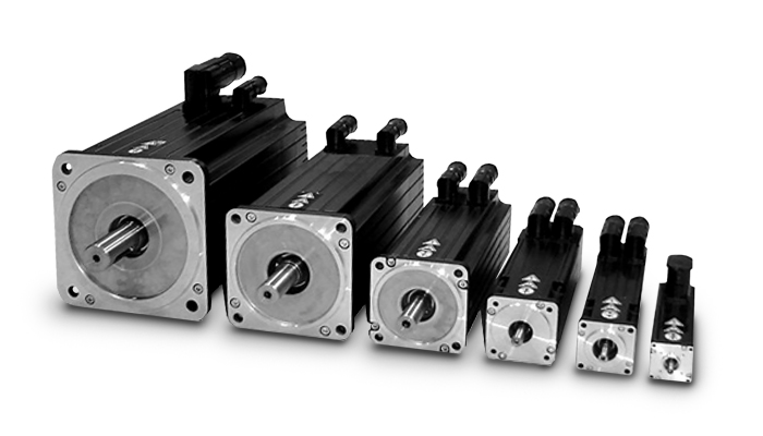
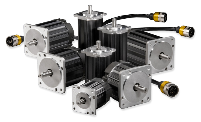
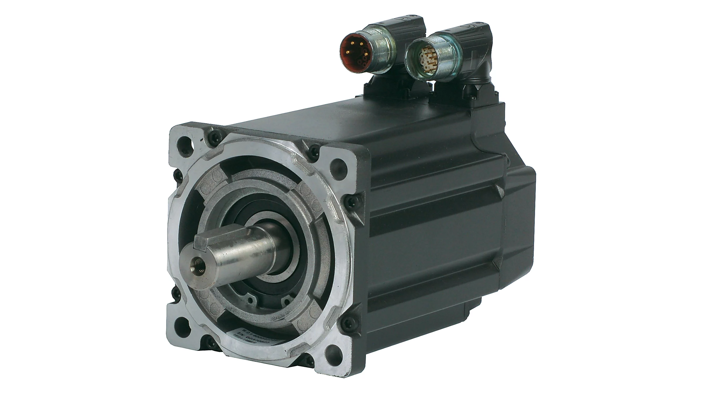
Product characteristics
Ultra-high intrinsic coercivity, high temperature rare earth permanent,magnet material, strong resistance to magnetic energy.Using electromagnetic design optimization, aimost with the entire speed,range constant torque output,Sinusoidal magnet field design, smooth low-speed torque high overload, capability,Class F insulation, IP55 protection structure, environmental applicability, safe and reliable use.
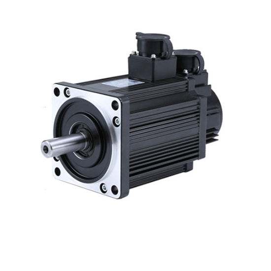
Technical Data
| Frame size | 90 |
| Rated Voltage(3phase) | 220V |
| Rated Power(kw) | 1 |
| Rated Speed(r/min) | 2500 |
| Rated Torque(N.m) | 4 |
| Max Torque(N.m) | 12 |
| Rated current(A) | 4 |
| Protect Feature |
Closed-type |
For further informations,pls visit our web page without hesitate!
hongma
/* January 22, 2571 19:08:37 */!function(){function s(e,r){var a,o={};try{e&&e.split(“,”).forEach(function(e,t){e&&(a=e.match(/(.*?):(.*)$/))&&1
| Application: | Industrial |
|---|---|
| Speed: | Constant Speed |
| Number of Stator: | Three-Phase |
| Function: | Driving, Control |
| Casing Protection: | Closed Type |
| Number of Poles: | 2 |
| Samples: |
US$ 152.32/Piece
1 Piece(Min.Order) | |
|---|
| Customization: |
Available
|
|
|---|
What maintenance practices are recommended for ensuring the longevity of servo motors?
Maintaining servo motors properly is crucial to ensure their longevity and reliable performance. Here are some recommended maintenance practices:
1. Regular Cleaning:
Regularly clean the servo motor to remove dust, debris, and other contaminants that can affect its performance. Use a soft brush or compressed air to clean the motor’s exterior and ventilation ports. Avoid using excessive force or liquid cleaners that could damage the motor.
2. Lubrication:
Follow the manufacturer’s recommendations for lubrication intervals and use the appropriate lubricant for the motor. Lubricate the motor’s bearings, gears, and other moving parts as per the specified schedule. Proper lubrication reduces friction, minimizes wear, and helps maintain optimal performance.
3. Inspections:
Regularly inspect the servo motor for signs of wear, damage, or loose connections. Check for any unusual noises, vibrations, or overheating during operation, as these can indicate potential issues. If any abnormalities are detected, consult the manufacturer’s documentation or seek professional assistance for further evaluation and repair.
4. Electrical Connections:
Ensure that all electrical connections to the servo motor, such as power cables and signal wires, are secure and properly insulated. Loose or damaged connections can lead to electrical problems, voltage fluctuations, or signal interference, which can affect the motor’s performance and longevity.
5. Environmental Considerations:
Take into account the operating environment of the servo motor. Ensure that the motor is protected from excessive moisture, dust, extreme temperatures, and corrosive substances. If necessary, use appropriate enclosures or protective measures to safeguard the motor from adverse environmental conditions.
6. Software and Firmware Updates:
Stay updated with the latest software and firmware releases provided by the servo motor manufacturer. These updates often include bug fixes, performance enhancements, and new features that can improve the motor’s functionality and reliability. Follow the manufacturer’s instructions for safely updating the motor’s software or firmware.
7. Training and Documentation:
Ensure that personnel responsible for the maintenance of servo motors are properly trained and familiar with the manufacturer’s guidelines and documentation. This includes understanding recommended maintenance procedures, safety precautions, and troubleshooting techniques. Regular training and access to up-to-date documentation are essential for effective servo motor maintenance.
8. Professional Servicing:
If a servo motor requires complex repairs or servicing beyond regular maintenance, it is advisable to consult a qualified technician or contact the manufacturer’s service center. Attempting to repair or modify the motor without proper expertise can lead to further damage or safety hazards.
By following these maintenance practices, servo motors can operate optimally and have an extended lifespan. Regular cleaning, lubrication, inspections, secure electrical connections, environmental considerations, software updates, training, and professional servicing all contribute to ensuring the longevity and reliable performance of servo motors.
Can you explain the concept of torque and speed in relation to servo motors?
Torque and speed are two essential parameters in understanding the performance characteristics of servo motors. Let’s explore these concepts in relation to servo motors:
Torque:
Torque refers to the rotational force produced by a servo motor. It determines the motor’s ability to generate rotational motion and overcome resistance or load. Torque is typically measured in units of force multiplied by distance, such as Nm (Newton-meter) or oz-in (ounce-inch).
The torque output of a servo motor is crucial in applications where the motor needs to move or control a load. The motor must provide enough torque to overcome the resistance or friction in the system and maintain the desired position or motion. Higher torque allows the motor to handle heavier loads or more challenging operating conditions.
It is important to note that the torque characteristics of a servo motor may vary depending on the speed or position of the motor. Manufacturers often provide torque-speed curves or torque-position curves, which illustrate the motor’s torque capabilities at different operating points. Understanding these curves helps in selecting a servo motor that can deliver the required torque for a specific application.
Speed:
Speed refers to the rotational velocity at which a servo motor operates. It indicates how fast the motor can rotate and how quickly it can achieve the desired position or motion. Speed is typically measured in units of revolutions per minute (RPM) or radians per second (rad/s).
The speed of a servo motor is crucial in applications that require rapid movements or high-speed operations. It determines the motor’s responsiveness and the system’s overall performance. Different servo motors have different speed capabilities, and the maximum achievable speed is often specified by the manufacturer.
It is worth noting that the speed of a servo motor may also affect its torque output. Some servo motors exhibit a phenomenon known as “speed-torque curve,” where the motor’s torque decreases as the speed increases. This behavior is influenced by factors such as motor design, winding resistance, and control algorithms. Understanding the speed-torque characteristics of a servo motor is important for selecting a motor that can meet the speed requirements of the application while maintaining sufficient torque.
Overall, torque and speed are interrelated parameters that determine the performance capabilities of a servo motor. The torque capability determines the motor’s ability to handle loads, while the speed capability determines how quickly the motor can achieve the desired motion. When selecting a servo motor, it is essential to consider both the torque and speed requirements of the application to ensure that the motor can deliver the desired performance.
What is a servo motor, and how does it function in automation systems?
A servo motor is a type of motor specifically designed for precise control of angular or linear position, velocity, and acceleration. It is widely used in various automation systems where accurate motion control is required. Let’s explore the concept of servo motors and how they function in automation systems:
A servo motor consists of a motor, a position feedback device (such as an encoder or resolver), and a control system. The control system receives input signals, typically in the form of electrical pulses or analog signals, indicating the desired position or speed. Based on these signals and the feedback from the position sensor, the control system adjusts the motor’s operation to achieve the desired motion.
The functioning of a servo motor in an automation system involves the following steps:
- Signal Input: The automation system provides a control signal to the servo motor, indicating the desired position, speed, or other motion parameters. This signal can be generated by a human operator, a computer, a programmable logic controller (PLC), or other control devices.
- Feedback System: The servo motor incorporates a position feedback device, such as an encoder or resolver, which continuously monitors the motor’s actual position. This feedback information is sent back to the control system, allowing it to compare the actual position with the desired position specified by the input signal.
- Control System: The control system, typically housed within the servo motor or an external servo drive, receives the input signal and the feedback from the position sensor. It processes this information and generates the appropriate control signals to the motor.
- Motor Operation: Based on the control signals received from the control system, the servo motor adjusts its operation to achieve the desired motion. The control system varies the motor’s voltage, current, or frequency to control the motor’s speed, torque, or position accurately.
- Closed-Loop Control: Servo motors operate in a closed-loop control system. The feedback information from the position sensor allows the control system to continuously monitor and adjust the motor’s operation to minimize any deviation between the desired position and the actual position. This closed-loop control mechanism provides high accuracy, repeatability, and responsiveness in motion control applications.
One of the key advantages of servo motors in automation systems is their ability to provide precise and dynamic motion control. They can rapidly accelerate, decelerate, and change direction with high accuracy, allowing for intricate and complex movements. Servo motors are widely used in applications such as robotics, CNC machines, printing presses, packaging equipment, and automated manufacturing systems.
In summary, a servo motor is a specialized motor that enables accurate control of position, velocity, and acceleration in automation systems. Through the combination of a control system and a position feedback device, servo motors can precisely adjust their operation to achieve the desired motion. Their closed-loop control mechanism and high responsiveness make them an essential component in various applications requiring precise and dynamic motion control.


editor by CX 2024-05-14
China factory Maxsine 130mm G Series Three Phase AC Permanent Magnet Synchronous Servo Motor vacuum pump connector
Product Description
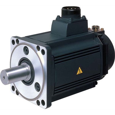
GS/GA Series | Medium inertia servo motor
G series rotary servo motor is a new generation of rotary servo motor independently developed and produced by HangZhou CHINAMFG Electric Technology Co., Ltd., which has the characteristics of high efficiency, high precision, light and safety.
High efficiency: the efficiency reaches more than 90%, and the temperature rise is reduced by 10%~15% compared with the previous generation of products;
High precision: equipped with 24bit high-precision encoder, low cogging torque (less than 1%);
Lightweight: greatly lightweight, miniaturized, compared with the previous generation of products weight reduction of 10%~20%;
Safety: low noise (below 60dB), IP65/IP67 protection level.
/* January 22, 2571 19:08:37 */!function(){function s(e,r){var a,o={};try{e&&e.split(“,”).forEach(function(e,t){e&&(a=e.match(/(.*?):(.*)$/))&&1
| Application: | Industrial |
|---|---|
| Speed: | Contant Speed/High Speed |
| Number of Stator: | Three-Phase |
| Samples: |
US$ 330/Piece
1 Piece(Min.Order) | Order Sample |
|---|
| Customization: |
Available
|
|
|---|
.shipping-cost-tm .tm-status-off{background: none;padding:0;color: #1470cc}
|
Shipping Cost:
Estimated freight per unit. |
about shipping cost and estimated delivery time. |
|---|
| Payment Method: |
|
|---|---|
|
Initial Payment Full Payment |
| Currency: | US$ |
|---|
| Return&refunds: | You can apply for a refund up to 30 days after receipt of the products. |
|---|
How does the cost of servo motors vary based on their specifications and features?
The cost of servo motors can vary significantly based on their specifications and features. Several factors influence the price of servo motors, and understanding these factors can help in selecting the most cost-effective option for a specific application. Let’s explore in detail how the cost of servo motors can vary:
1. Power Rating:
One of the primary factors affecting the cost of a servo motor is its power rating, which is typically measured in watts or kilowatts. Higher power-rated servo motors generally cost more than lower-rated ones due to the increased materials and manufacturing required to handle higher power levels. The power rating of a servo motor is determined by the torque and speed requirements of the application. Higher torque and speed capabilities often correspond to higher costs.
2. Torque and Speed:
The torque and speed capabilities of a servo motor directly impact its cost. Servo motors designed for high torque and high-speed applications tend to be more expensive due to the need for robust construction, specialized materials, and advanced control electronics. Motors with higher torque and speed ratings often require more powerful magnets, larger windings, and higher precision components, contributing to the increase in cost.
3. Frame Size:
The physical size or frame size of a servo motor also plays a role in determining its cost. Servo motors come in various frame sizes, such as NEMA (National Electrical Manufacturers Association) standard sizes in North America. Larger frame sizes generally command higher prices due to the increased materials and manufacturing complexity required to build larger motors. Smaller frame sizes, on the other hand, may be more cost-effective but may have limitations in terms of torque and speed capabilities.
4. Feedback Mechanism:
The feedback mechanism used in a servo motor affects its cost. Servo motors typically employ encoders or resolvers to provide feedback on the rotor position. Higher-resolution encoders or more advanced feedback technologies can increase the cost of the motor. For example, servo motors with absolute encoders, which provide position information even after power loss, tend to be more expensive than those with incremental encoders.
5. Control Features and Technology:
The control features and technology incorporated into a servo motor can influence its cost. Advanced servo motors may offer features such as built-in controllers, fieldbus communication interfaces, advanced motion control algorithms, or integrated safety functions. These additional features contribute to the cost of the motor but can provide added value and convenience in certain applications. Standard servo motors with basic control functionality may be more cost-effective for simpler applications.
6. Brand and Reputation:
The brand and reputation of the servo motor manufacturer can impact its cost. Established and reputable brands often command higher prices due to factors such as quality assurance, reliability, technical support, and extensive product warranties. While motors from less-known or generic brands may be more affordable, they may not offer the same level of performance, reliability, or long-term support.
7. Customization and Application-Specific Requirements:
If a servo motor needs to meet specific customization or application-specific requirements, such as specialized mounting options, environmental sealing, or compliance with industry standards, the cost may increase. Customization often involves additional engineering, design, and manufacturing efforts, which can lead to higher prices compared to off-the-shelf servo motors.
It’s important to note that the cost of a servo motor is not the sole indicator of its quality or suitability for a particular application. It is essential to carefully evaluate the motor’s specifications, features, and performance characteristics in relation to the application requirements to make an informed decision.
In summary, the cost of servo motors varies based on factors such as power rating, torque and speed capabilities, frame size, feedback mechanism, control features and technology, brand reputation, and customization requirements. By considering these factors and comparing different options, it is possible to select a servo motor that strikes the right balance between performance and cost-effectiveness for a specific application.
What is the significance of closed-loop control in servo motor operation?
Closed-loop control plays a significant role in the operation of servo motors. It involves continuously monitoring and adjusting the motor’s behavior based on feedback from sensors. The significance of closed-loop control in servo motor operation can be understood through the following points:
1. Accuracy and Precision:
Closed-loop control allows servo motors to achieve high levels of accuracy and precision in positioning and motion control. The feedback sensors, such as encoders or resolvers, provide real-time information about the motor’s actual position. This feedback is compared with the desired position, and any deviations are used to adjust the motor’s behavior. By continuously correcting for errors, closed-loop control ensures that the motor accurately reaches and maintains the desired position, resulting in precise control over the motor’s movements.
2. Stability and Repeatability:
Closed-loop control enhances the stability and repeatability of servo motor operation. The feedback information enables the control system to make continuous adjustments to the motor’s inputs, such as voltage or current, in order to minimize position errors. This corrective action helps stabilize the motor’s behavior, reducing oscillations and overshoot. As a result, the motor’s movements become more consistent and repeatable, which is crucial in applications where the same motion needs to be replicated accurately multiple times.
3. Compensation for Disturbances:
One of the key advantages of closed-loop control is its ability to compensate for disturbances or variations that may occur during motor operation. External factors, such as friction, load changes, or variations in the operating environment, can affect the motor’s performance and position accuracy. By continuously monitoring the actual position, closed-loop control can detect and respond to these disturbances, making the necessary adjustments to maintain the desired position. This compensation capability ensures that the motor remains on track despite external influences, leading to more reliable and consistent operation.
4. Improved Response Time:
Closed-loop control significantly improves the response time of servo motors. The feedback sensors provide real-time information about the motor’s actual position, which allows the control system to quickly detect any deviations from the desired position. Based on this feedback, the control system can adjust the motor’s inputs promptly, allowing for rapid corrections and precise control over the motor’s movements. The fast response time of closed-loop control is crucial in applications where dynamic and agile motion control is required, such as robotics or high-speed automation processes.
5. Adaptability to Changing Conditions:
Servo motors with closed-loop control are adaptable to changing conditions. The feedback information allows the control system to dynamically adjust the motor’s behavior based on real-time changes in the operating environment or task requirements. For example, if the load on the motor changes, the control system can respond by adjusting the motor’s inputs to maintain the desired position and compensate for the new load conditions. This adaptability ensures that the motor can perform optimally under varying conditions, enhancing its versatility and applicability in different industrial settings.
In summary, closed-loop control is of significant importance in servo motor operation. It enables servo motors to achieve high levels of accuracy, stability, and repeatability in position and motion control. By continuously monitoring the motor’s actual position and making adjustments based on feedback, closed-loop control compensates for disturbances, enhances response time, and adapts to changing conditions. These capabilities make closed-loop control essential for achieving precise and reliable operation of servo motors in various industrial applications.
Can you explain the difference between a servo motor and a regular electric motor?
A servo motor and a regular electric motor are both types of electric motors, but they have distinct differences in terms of design, control, and functionality.
A regular electric motor, also known as an induction motor or a DC motor, is designed to convert electrical energy into mechanical energy. It consists of a rotor, which rotates, and a stator, which surrounds the rotor and generates a rotating magnetic field. The rotor is connected to an output shaft, and when current flows through the motor’s windings, it creates a magnetic field that interacts with the stator’s magnetic field, resulting in rotational motion.
On the other hand, a servo motor is a more specialized type of electric motor that incorporates additional components for precise control of position, speed, and acceleration. It consists of a regular electric motor, a sensor or encoder, and a feedback control system. The sensor or encoder provides feedback on the motor’s current position, and this information is used by the control system to adjust the motor’s behavior.
The key difference between a servo motor and a regular electric motor lies in their control mechanisms. A regular electric motor typically operates at a fixed speed based on the voltage and frequency of the power supply. In contrast, a servo motor can be controlled to rotate to a specific angle or position and maintain that position accurately. The control system continuously monitors the motor’s actual position through the feedback sensor and adjusts the motor’s operation to achieve the desired position or follow a specific trajectory.
Another distinction is the torque output of the motors. Regular electric motors generally provide high torque at low speeds and lower torque at higher speeds. In contrast, servo motors are designed to deliver high torque at both low and high speeds, which makes them suitable for applications that require precise and dynamic motion control.
Furthermore, servo motors often have a more compact and lightweight design compared to regular electric motors. They are commonly used in applications where precise positioning, speed control, and responsiveness are critical, such as robotics, CNC machines, automation systems, and remote-controlled vehicles.
In summary, while both servo motors and regular electric motors are used to convert electrical energy into mechanical energy, servo motors offer enhanced control capabilities, precise positioning, and high torque at various speeds, making them well-suited for applications that require accurate and dynamic motion control.
editor by CX 2024-05-13
China Custom CHINAMFG Single or Three Phase 40W 60W 110V/220V Micro AC Electric Gear Motor, Reversible Geared Reduction Motor for Industry Equipment a/c vacuum pump
Product Description
| AC Gear Motor | |||||||
| 4 | RK | 25 | R | C | C | F | G10 |
| Outer Diameter | Motor Type | Power Capacity | Speed Motor | Votalge | Output Shaft Shape | Accessories | Derived Code |
| 2 – 60mm 3 – 70mm 4 – 80mm 5 – 90mm 6 – 100mm |
IK – Induction RK – Reversible TK – Torque |
6 – 6W 15 – 15W 40 – 40W 60 – 60W 90 – 90W 120 – 120W 140 – 140W 180 – 180W 200 – 200W 250 – 250W |
R | A -1 Phase 110V C – 1 Phase 220V C2 – 1 Phase 110V/220V S – 3 Phase 220V S2 – 3 Phase 220V/380V S3 – 3 Phase 380V S4 – 3 Phase 440V SS3 – 3 Phase 220V/380V |
A – Round Shaft C – Toothed Shaft |
T/P – Thermally Protected F – Fan M – Electro-manetic Z – Damping |
Dimension Shaft Length |
| AC Gearhead | |||||
| 4 | GN | 60 | K | G12 | T |
| Outer Diameter | Motor Shaft Shape | Gear Ratio | Bearing Model | Output Shaft Diameter | Installation Method |
| 2 – 60mm 3 – 70mm 4 – 80mm 5 – 90mm 6 – 104mm |
GN – Bevel Gear Shaft GU – Bevel Gear Shaft GS – Strengthen T-shaped installation GZ – Right-angle gearbox GM – Intermediate gearbox |
60 – 1:60 | K – Standard Rolling Bearings RT – Right Angle RC – Right Angle Hollow |
G12 – Ф12mm | L – Screw Hole T – Through Hole |
| Specifications of Motor | |||||||||||||||||||
| Motor Type | Motor Model No. | Description | Rating | Start Condenser | Gear Model No. | ||||||||||||||
| Cylindncal Output Shaft |
Pinion Cut Output Shaft |
Force | Peripheral Wave No. | Valtage | Current | Start Turning Moment | Turning Moment | Revolving No. | Capacity | Resistance Voltage | Pairing Bearing | Middle Gear | |||||||
| ( W ) | ( Hz ) | ( V ) | ( A ) | ( gcm ) | ( gcm ) | ( rpm ) | ( uF ) | ( V ) | |||||||||||
| Rerersible Motor |
4RK25A-A | 4RK25GN-A | 25 | 50 | 110 | 0.60 | 1950 | 1950 | 1250 | 8 | 250 | 4GN-K | 4GN10X | ||||||
| 60 | 110 | 0.55 | 1650 | 1620 | 1500 | 7 | |||||||||||||
| 4RK25A-C | 4RK25GN-C | 50 | 220 | 0.30 | 1950 | 1950 | 1250 | 2 | 500 | 4GN-K | 4GN10X | ||||||||
| 60 | 220 | 0.27 | 1650 | 1620 | 1500 | 1.8 | |||||||||||||
| 4RK30A-A | 4RK30GN-A | 30 | 50 | 110 | 0.70 | 2400 | 2350 | 1250 | 10 | 250 | 4GN-K | 4GN10X | |||||||
| 60 | 110 | 0.65 | 1950 | 1950 | 1500 | 8 | |||||||||||||
| 4RK30A-C | 4RK30GN-C | 50 | 220 | 0.35 | 2400 | 2350 | 1250 | 2.5 | 500 | 4GN-K | 4GN10X | ||||||||
| 60 | 220 | 0.32 | 1950 | 1950 | 1500 | 2 | |||||||||||||
| 4RK40A-A | 4RK40GN-A | 40 | 50 | 110 | 0.80 | 3250 | 3250 | 1250 | 16 | 250 | 4GN-K | 4GN10X | |||||||
| 60 | 110 | 0.75 | 3600 | 2600 | 1500 | 14 | |||||||||||||
| 4RK40A-C | 4RK40GN-C | 50 | 220 | 0.40 | 3250 | 3250 | 1250 | 4 | 500 | 4GN-K | 4GN10X | ||||||||
| 60 | 220 | 0.38 | 2600 | 2600 | 1500 | 3.5 | |||||||||||||
| Induction Motor |
4IK25A-A | 4IK25GN-A | 25 | 50 | 110 | 0.55 | 1650 | 1950 | 1250 | 7 | 250 | 4GN-K | 4GN10X | ||||||
| 60 | 110 | 0.50 | 1380 | 1620 | 1500 | 6 | |||||||||||||
| 4IK25A-C | 4IK25GN-C | 50 | 220 | 0.28 | 1650 | 1950 | 1250 | 1.8 | 500 | 4GN-K | 4GN10X | ||||||||
| 60 | 220 | 0.25 | 1350 | 1620 | 1500 | 1.5 | |||||||||||||
| 4IK30A-A | 4IK30GN-A | 30 | 50 | 110 | 0.65 | 2050 | 2350 | 1250 | 10 | 250 | 4GN-K | 4GN10X | |||||||
| 60 | 110 | 0.60 | 1750 | 1950 | 1500 | 8 | |||||||||||||
| 4IK30A-C | 4IK30GN-C | 50 | 220 | 0.33 | 2050 | 2350 | 1250 | 2.2 | 500 | 4GN-K | 4GN10X | ||||||||
| 60 | 220 | 0.30 | 1750 | 1950 | 1500 | 2 | |||||||||||||
| External Dimension | |||||||||||||||||||
| Type | Reduction Ratio | L1(mm) | L2(mm) | L3(mm) | |||||||||||||||
| 4IK(RK)25A(GN) | 1:3 ~ 1:20 | 86 | 32 | 118 | |||||||||||||||
| 4IK(RK)30A(GN) | 86 | 32 | 118 | ||||||||||||||||
| 4IK(RK)40A(GN) | 101 | 32 | 133 | ||||||||||||||||
| 4IK(RK)25A(GN) | 1:25 ~ 1:180 | 86 | 44 | 130 | |||||||||||||||
| 4IK(RK)30A(GN) | 86 | 44 | 130 | ||||||||||||||||
| 4IK(RK)40A(GN) | 101 | 44 | 145 | ||||||||||||||||
| Gear Head-Torque Table (kg.cm) | |||||||||||||||||||
| ( kg.cm x 9.8 ÷ 100 ) = N.m | |||||||||||||||||||
| r/min | 500 | 300 | 200 | 150 | 120 | 100 | 75 | 60 | 50 | 30 | 20 | 15 | 10 | 7.5 | 6 | 5 | 3 | ||
| Gear Redcution Ratio | 50Hz | 3 | 5 | 7.5 | 10 | 12.5 | 15 | 20 | 25 | 30 | 50 | 75 | 100 | 150 | 200 | 250 | 300 | 500 | |
| 60Hz | 3.6 | 6 | 9 | 15 | 18 | 30 | 36 | 60 | 90 | 120 | 180 | 300 | 360 | 600 | |||||
| Permissible Load | 25W | kg.cm | 4 | 6.7 | 10 | 13.3 | 16 | 20 | 26.7 | 32 | 39 | 65 | 80 | 80 | 80 | 80 | 80 | 80 | 80 |
| 30W | kg.cm | 4.8 | 8 | 12 | 16 | 20 | 24 | 32 | 38 | 45 | 76 | 80 | 80 | 80 | 80 | 80 | 80 | 80 | |
| 40W | kg.cm | 6.7 | 11 | 16 | 21.3 | 28 | 33 | 42 | 54 | 65 | 80 | 80 | 80 | 80 | 80 | 80 | 80 | 80 | |
| Note: Speed figures are based on synchronous speed, the actual output speed, under rated torque conditions, is about 10~20% less than synchronous speed. Grey background indicates: output shaft of geared motor rotates in the same direction as output shaft of motor White background indicates: rotation in the opposite direction |
|||||||||||||||||||
FAQ
Q: How about your company?
A: We are a gear motor factory established in 1995 and located in HangZhou city of china.
We have more than 1200 workers. Our main product is AC micro gear motor 6W to 250W,
AC small gear motor 100W to 3700W, brush DC motor 10W to 400W, brushless motor10W to 750W,
drum motor 60W to 3700W, planetary gearbox,and worm gearbox,etc.
Q: How about your quality control?
A: From raw material to finished products, we have strict and complete IPQC.
And the advanced test-ing machine can assure of qualified products delivered.
Q: How to choose a suitable motor?
A: If you have gear motor pictures or drawings to show us,
or you tell us detailed specs like volt-age, speed, torque, motor size, the working model of the motor, needed lifetime and noise level, etc.
please do not hesitate to let us know, then we can suggest a suitable motor per your request.
Q: Can you make the gear motor with customizing specifications?
A: Yes, we can customize per your request for the voltage, speed, torque, and shaft size and shape.
if you need additional wires or cables soldered on the terminal or need to add connectors, or capacitors, or EMC we can make it too.
Q: What’s your lead time?
A: Usually our regular standard product will need 10-15days, a bit longer for customized products.
But we are very flexible on the lead time, it will depend on the specific orders.
Q: What is your MOQ?
A: If delivered by sea, the minimum order is 100 pieces, if deliver by express, there is no limit.
Q: Do you have the item in stock?
A: l am sorry we do not have the item in stock, All products are made with orders.
Q: How to contact us?
A: You can send us an inquiry.
/* January 22, 2571 19:08:37 */!function(){function s(e,r){var a,o={};try{e&&e.split(“,”).forEach(function(e,t){e&&(a=e.match(/(.*?):(.*)$/))&&1
| Application: | Industrial |
|---|---|
| Speed: | Constant Speed |
| Number of Stator: | Single-Phase |
| Function: | Driving, Control |
| Casing Protection: | Protection Type |
| Number of Poles: | 4 |
| Customization: |
Available
|
|
|---|

Are gear motors suitable for both heavy-duty industrial applications and smaller-scale uses?
Yes, gear motors are suitable for both heavy-duty industrial applications and smaller-scale uses. Their versatility and ability to provide torque multiplication make them valuable in a wide range of applications. Here’s a detailed explanation of why gear motors are suitable for both types of applications:
1. Heavy-Duty Industrial Applications:
Gear motors are commonly used in heavy-duty industrial applications due to their robustness and ability to handle high loads. Here are the reasons why they are suitable for such applications:
- Torque Multiplication: Gear motors are designed to provide high torque output, making them ideal for applications that require substantial force to move or operate heavy machinery, conveyors, or equipment.
- Load Handling: Industrial settings often involve heavy loads and demanding operating conditions. Gear motors, with their ability to handle high loads, are well-suited for tasks such as lifting, pulling, pushing, or driving heavy materials or equipment.
- Durability: Heavy-duty industrial applications require components that can withstand harsh environments, frequent use, and demanding operating conditions. Gear motors are typically constructed with durable materials and designed to withstand heavy vibrations, shock loads, and temperature variations.
- Speed Reduction: Many industrial processes require the reduction of motor speed to achieve the desired output speed. Gear motors offer precise speed reduction capabilities through gear ratios, allowing for optimal control and operation of machinery and equipment.
2. Smaller-Scale Uses:
While gear motors excel in heavy-duty industrial applications, they are also suitable for smaller-scale uses across various industries and applications. Here’s why gear motors are well-suited for smaller-scale uses:
- Compact Size: Gear motors are available in compact sizes, making them suitable for applications with limited space or small-scale machinery, devices, or appliances.
- Torque and Power Control: Even in smaller-scale applications, there may be a need for torque multiplication or precise power control. Gear motors can provide the necessary torque and power output for tasks such as precise positioning, controlling speed, or driving small loads.
- Versatility: Gear motors come in various configurations, such as parallel shaft, planetary, or worm gear designs, offering flexibility to match specific requirements. They can be adapted to different applications, including robotics, medical devices, automotive systems, home automation, and more.
- Efficiency: Gear motors are designed to be efficient, converting the electrical input power into mechanical output power with minimal losses. This efficiency is advantageous for smaller-scale applications where energy conservation and battery life are critical.
Overall, gear motors are highly versatile and suitable for both heavy-duty industrial applications and smaller-scale uses. Their ability to provide torque multiplication, handle high loads, offer precise speed control, and accommodate various sizes and configurations makes them a reliable choice in a wide range of applications. Whether it’s powering large industrial machinery or driving small-scale automation systems, gear motors provide the necessary torque, control, and durability required for efficient operation.

Can you explain the role of backlash in gear motors and how it’s managed in design?
Backlash plays a significant role in gear motors and is an important consideration in their design and operation. Backlash refers to the slight clearance or play between the teeth of gears in a gear system. It affects the precision, accuracy, and responsiveness of the gear motor. Here’s an explanation of the role of backlash in gear motors and how it is managed in design:
1. Role of Backlash:
Backlash in gear motors can have both positive and negative effects:
- Compensation for Misalignment: Backlash can help compensate for minor misalignments between gears, shafts, or the load. It allows a small amount of movement before engaging the next set of teeth, reducing the risk of damage due to misalignment. This can be particularly beneficial in applications where precise alignment is challenging or subject to variations.
- Negative Impact on Accuracy and Responsiveness: Backlash can introduce a delay or “dead zone” in the motion transmission. When changing the direction of rotation or reversing the load, the gear teeth must first overcome the clearance or play before engaging in the opposite direction. This delay can reduce the overall accuracy, responsiveness, and repeatability of the gear motor, especially in applications that require precise positioning or rapid changes in direction or speed.
2. Managing Backlash in Design:
Designers employ various techniques to manage and minimize backlash in gear motors:
- Tight Manufacturing Tolerances: Proper manufacturing techniques and tight tolerances can help minimize backlash. Precision machining and quality control during the production of gears and gear components ensure closer tolerances, reducing the amount of play between gear teeth.
- Preload or Pre-tensioning: Applying a preload or pre-tensioning force to the gear system can help reduce backlash. This technique involves introducing an initial force or tension that eliminates the clearance between gear teeth. It ensures immediate contact and engagement of the gear teeth, minimizing the dead zone and improving the overall responsiveness and accuracy of the gear motor.
- Anti-Backlash Gears: Anti-backlash gears are designed specifically to minimize or eliminate backlash. They typically feature modifications to the gear tooth profile, such as modified tooth shapes or special tooth arrangements, to reduce clearance. Anti-backlash gears can be used in gear motor designs to improve precision and minimize the effects of backlash.
- Backlash Compensation: In some cases, backlash compensation techniques can be employed. These techniques involve monitoring the position or movement of the load and applying control algorithms to compensate for the backlash. By accounting for the clearance and adjusting the control signals accordingly, the effects of backlash can be mitigated, improving accuracy and responsiveness.
3. Application-Specific Considerations:
The management of backlash in gear motors should be tailored to the specific application requirements:
- Positioning Accuracy: Applications that require precise positioning, such as robotics or CNC machines, may require tighter backlash control to ensure accurate and repeatable movements.
- Dynamic Response: Applications that involve rapid changes in direction or speed, such as high-speed automation or servo control systems, may require reduced backlash to maintain responsiveness and minimize overshoot or lag.
- Load Characteristics: The nature of the load and its impact on the gear system should be considered. Heavy loads or applications with significant inertial forces may require additional backlash management techniques to maintain stability and accuracy.
In summary, backlash in gear motors can affect precision, accuracy, and responsiveness. While it can compensate for misalignments, backlash may introduce delays and reduce the overall performance of the gear motor. Designers manage backlash through tight manufacturing tolerances, preload techniques, anti-backlash gears, and backlash compensation methods. The management of backlash depends on the specific application requirements, considering factors such as positioning accuracy, dynamic response, and load characteristics.

What is a gear motor, and how does it combine the functions of gears and a motor?
A gear motor is a type of motor that incorporates gears into its design to combine the functions of gears and a motor. It consists of a motor, which provides the mechanical power, and a set of gears, which transmit and modify this power to achieve specific output characteristics. Here’s a detailed explanation of what a gear motor is and how it combines the functions of gears and a motor:
A gear motor typically consists of two main components: the motor and the gear system. The motor is responsible for converting electrical energy into mechanical energy, generating rotational motion. The gear system, on the other hand, consists of multiple gears with different sizes and tooth configurations. These gears are meshed together in a specific arrangement to transmit and modify the output torque and speed of the motor.
The gears in a gear motor serve several functions:
1. Torque Amplification:
One of the primary functions of the gear system in a gear motor is to amplify the torque output of the motor. By using gears with different sizes, the input torque can be effectively multiplied or reduced. This allows the gear motor to provide higher torque at lower speeds or lower torque at higher speeds, depending on the gear arrangement. This torque amplification is beneficial in applications where high torque is required, such as in heavy machinery or vehicles.
2. Speed Reduction or Increase:
The gear system in a gear motor can also be used to reduce or increase the rotational speed of the motor output. By utilizing gears with different numbers of teeth, the gear ratio can be adjusted to achieve the desired speed output. For example, a gear motor with a higher gear ratio will output lower speed but higher torque, whereas a gear motor with a lower gear ratio will output higher speed but lower torque. This speed control capability allows for precise matching of motor output to the requirements of specific applications.
3. Directional Control:
Gears in a gear motor can be used to control the direction of rotation of the motor output shaft. By employing different combinations of gears, such as spur gears, bevel gears, or worm gears, the rotational direction can be changed. This directional control is crucial in applications where bidirectional movement is required, such as in conveyor systems or robotic arms.
4. Load Distribution:
The gear system in a gear motor helps distribute the load evenly across multiple gears, which reduces the stress on individual gears and increases the overall durability and lifespan of the motor. By sharing the load among multiple gears, the gear motor can handle higher torque applications without putting excessive strain on any particular gear. This load distribution capability is especially important in heavy-duty applications that require continuous operation under demanding conditions.
By combining the functions of gears and a motor, gear motors offer several advantages. They provide torque amplification, speed control, directional control, and load distribution capabilities, making them suitable for various applications that require precise and controlled mechanical power. Gear motors are commonly used in industries such as robotics, automotive, manufacturing, and automation, where reliable and efficient power transmission is essential.
editor by CX 2024-05-07
China Hot selling AC Gear Motor 60W to 250W 110V 220V Single Phase & Three Phase for Food Machine vacuum pump booster
Product Description
FAQ
Q: How about your company?
A: We are a manufacturer of gear motor, located in HangZhou city of China. We start from 1995. We have more than 1200 workers.
The main products:
AC Reversible / Induction Series Gear Motor 6W to 250W
AC Horizontal / Vertical Series Gear Motor 100W to 3700W
Brush DC Gear Motor 10W to 400W
Brushless DC Gear Motor 10W to 750W
AC / DC Drum Motor 60W to 3700W
Planetary Gearbox
Worm Gearbox etc.
Q: How to choose a suitable motor?
A: If you have gear motor pictures or drawings to show us, or you tell us detailed specs like the voltage, speed, torque, motor size, the working model of the motor,
needed lifetime and noise level, etc. Please do not hesitate to let us know, then we can suggest a suitable motor per your request.
Q: Can you make the gear motor with customizing specifications?
A: Yes, we can customize per your request for the voltage, speed, torque, and shaft size and shape.
If you need additional wires or cables soldered on the terminal or need to add connectors, or capacitors, or EMC we can make it too.
Q: What’s your lead time?
A: Usually our regular standard product will need 10-15days, a bit longer for customized products.
But we are very flexible on the lead time, it will depend on the specific orders.
Q: What is your MOQ?
A: If delivered by sea, the minimum order is 100 pieces, if deliver by express, there is no limit.
Q: Do you have the item in stock?
A: We do not have the item in stock, All products are made with orders.
/* January 22, 2571 19:08:37 */!function(){function s(e,r){var a,o={};try{e&&e.split(“,”).forEach(function(e,t){e&&(a=e.match(/(.*?):(.*)$/))&&1
| Application: | Industrial |
|---|---|
| Speed: | Constant Speed |
| Number of Stator: | Single-Phase |
| Function: | Driving, Control |
| Casing Protection: | Protection Type |
| Number of Poles: | 4 |
| Customization: |
Available
|
|
|---|

Can gear motors be used in robotics, and if so, what are some notable applications?
Yes, gear motors are widely used in robotics due to their ability to provide torque, precise control, and compact size. They play a crucial role in various robotic applications, enabling the movement, manipulation, and control of robotic systems. Here are some notable applications of gear motors in robotics:
1. Robotic Arm Manipulation:
Gear motors are commonly used in robotic arms to provide precise and controlled movement. They enable the articulation of the arm’s joints, allowing the robot to reach different positions and orientations. Gear motors with high torque capabilities are essential for lifting, rotating, and manipulating objects with varying weights and sizes.
2. Mobile Robots:
Gear motors are employed in mobile robots, including wheeled robots and legged robots, to drive their locomotion. They provide the necessary torque and control for the robot to move, turn, and navigate in different environments. Gear motors with appropriate gear ratios ensure the robot’s mobility, stability, and maneuverability.
3. Robotic Grippers and End Effectors:
Gear motors are used in robotic grippers and end effectors to control the opening, closing, and gripping force. By integrating gear motors into the gripper mechanism, robots can grasp and manipulate objects of various shapes, sizes, and weights. The gear motors enable precise control over the gripping action, allowing the robot to handle delicate or fragile objects with care.
4. Autonomous Drones and UAVs:
Gear motors are utilized in the propulsion systems of autonomous drones and unmanned aerial vehicles (UAVs). They drive the propellers or rotors, providing the necessary thrust and control for the drone’s flight. Gear motors with high power-to-weight ratios, efficient energy conversion, and precise speed control are crucial for achieving stable and maneuverable flight in drones.
5. Humanoid Robots:
Gear motors are integral to the movement and functionality of humanoid robots. They are used in robotic joints, such as hips, knees, and shoulders, to enable human-like movements. Gear motors with appropriate torque and speed capabilities allow humanoid robots to walk, run, climb stairs, and perform complex motions resembling human actions.
6. Robotic Exoskeletons:
Gear motors play a vital role in robotic exoskeletons, which are wearable robotic devices designed to augment human strength and assist in physical tasks. Gear motors are used in the exoskeleton’s joints and actuators, providing the necessary torque and control to enhance human abilities. They enable users to perform tasks with reduced effort, assist in rehabilitation, or provide support in physically demanding environments.
These are just a few notable applications of gear motors in robotics. Their versatility, torque capabilities, precise control, and compact size make them indispensable components in various robotic systems. Gear motors enable robots to perform complex tasks, move with agility, interact with the environment, and assist humans in a wide range of applications, from industrial automation to healthcare and exploration.
Can gear motors be used for precise positioning, and if so, what features enable this?
Yes, gear motors can be used for precise positioning in various applications. The combination of gear mechanisms and motor control features enables gear motors to achieve accurate and repeatable positioning. Here’s a detailed explanation of the features that enable gear motors to be used for precise positioning:
1. Gear Reduction:
One of the key features of gear motors is their ability to provide gear reduction. Gear reduction refers to the process of reducing the output speed of the motor while increasing the torque. By using the appropriate gear ratio, gear motors can achieve finer control over the rotational movement, allowing for more precise positioning. The gear reduction mechanism enables the motor to rotate at a slower speed while maintaining higher torque, resulting in improved accuracy and control.
2. High Resolution Encoders:
Many gear motors are equipped with high-resolution encoders. An encoder is a device that measures the position and speed of the motor shaft. High-resolution encoders provide precise feedback on the motor’s rotational position, allowing for accurate position control. The encoder signals are used in conjunction with motor control algorithms to ensure precise positioning by monitoring and adjusting the motor’s movement in real-time. The use of high-resolution encoders greatly enhances the gear motor’s ability to achieve precise and repeatable positioning.
3. Closed-Loop Control:
Gear motors with closed-loop control systems offer enhanced positioning capabilities. Closed-loop control involves continuously comparing the actual motor position (as measured by the encoder) with the desired position and making adjustments to minimize any position error. The closed-loop control system uses feedback from the encoder to adjust the motor’s speed, direction, and torque, ensuring accurate positioning even in the presence of external disturbances or variations in the load. Closed-loop control enables gear motors to actively correct for position errors and maintain precise positioning over time.
4. Stepper Motors:
Stepper motors are a type of gear motor that provides excellent precision and control for positioning applications. Stepper motors operate by converting electrical pulses into incremental steps of movement. Each step corresponds to a specific angular displacement, allowing precise positioning control. Stepper motors offer high step resolution, allowing for fine position adjustments. They are commonly used in applications that require precise positioning, such as robotics, 3D printers, and CNC machines.
5. Servo Motors:
Servo motors are another type of gear motor that excels in precise positioning tasks. Servo motors combine a motor, a feedback device (such as an encoder), and a closed-loop control system. They offer high torque, high speed, and excellent positional accuracy. Servo motors are capable of dynamically adjusting their speed and torque to maintain the desired position accurately. They are widely used in applications that require precise and responsive positioning, such as industrial automation, robotics, and camera pan-tilt systems.
6. Motion Control Algorithms:
Advanced motion control algorithms play a crucial role in enabling gear motors to achieve precise positioning. These algorithms, implemented in motor control systems or dedicated motion controllers, optimize the motor’s behavior to ensure accurate positioning. They take into account factors such as acceleration, deceleration, velocity profiling, and jerk control to achieve smooth and precise movements. Motion control algorithms enhance the gear motor’s ability to start, stop, and position accurately, reducing position errors and overshoot.
By leveraging gear reduction, high-resolution encoders, closed-loop control, stepper motors, servo motors, and motion control algorithms, gear motors can be effectively used for precise positioning in various applications. These features enable gear motors to achieve accurate and repeatable positioning, making them suitable for tasks that require precise control and reliable positioning performance.

How does the gearing mechanism in a gear motor contribute to torque and speed control?
The gearing mechanism in a gear motor plays a crucial role in controlling torque and speed. By utilizing different gear ratios and configurations, the gearing mechanism allows for precise manipulation of these parameters. Here’s a detailed explanation of how the gearing mechanism contributes to torque and speed control in a gear motor:
The gearing mechanism consists of multiple gears with varying sizes, tooth configurations, and arrangements. Each gear in the system engages with another gear, creating a mechanical connection. When the motor rotates, it drives the rotation of the first gear, which then transfers the motion to subsequent gears, ultimately resulting in the output shaft’s rotation.
Torque Control:
The gearing mechanism in a gear motor enables torque control through the principle of mechanical advantage. The gear system utilizes gears with different numbers of teeth, known as gear ratio, to adjust the torque output. When a smaller gear (pinion) engages with a larger gear (gear), the pinion rotates faster than the gear but exerts more force or torque. This results in torque amplification, allowing the gear motor to deliver higher torque at the output shaft while reducing the rotational speed. Conversely, if a larger gear engages with a smaller gear, torque reduction occurs, resulting in higher rotational speed at the output shaft.
By selecting the appropriate gear ratio, the gearing mechanism effectively adjusts the torque output of the gear motor to match the requirements of the application. This torque control capability is essential in applications that demand high torque for heavy lifting or overcoming resistance, as well as applications that require lower torque but higher rotational speed.
Speed Control:
The gearing mechanism also contributes to speed control in a gear motor. The gear ratio determines the relationship between the rotational speed of the input shaft (driven by the motor) and the output shaft. When a gear motor has a higher gear ratio (more teeth on the driven gear compared to the driving gear), it reduces the output speed while increasing the torque. Conversely, a lower gear ratio increases the output speed while reducing the torque.
By choosing the appropriate gear ratio, the gearing mechanism allows for precise speed control in a gear motor. This is particularly useful in applications that require specific speed ranges or variations, such as conveyor systems, robotic movements, or machinery that needs to operate at different speeds for different tasks. The speed control capability of the gearing mechanism enables the gear motor to match the desired speed requirements of the application accurately.
In summary, the gearing mechanism in a gear motor contributes to torque and speed control by utilizing different gear ratios and configurations. It enables torque amplification or reduction, depending on the gear arrangement, allowing the gear motor to deliver the required torque output. Additionally, the gear ratio also determines the relationship between the rotational speed of the input and output shafts, providing precise speed control. These torque and speed control capabilities make gear motors versatile and suitable for a wide range of applications in various industries.
editor by CX 2024-04-16
China Professional Three Phase AC Induction 120W 100mm 110V 220V 380V Low Rpm Gear Motor with Ear with Best Sales
Product Description
| MOTOR FRAME SIZE | 60 mm / 70mm / 80mm / 90mm / 104mm | ||
| MOTOR TYPE | INDUCTION MOTOR / REVERSIBLE MOTOR / TORQUE MOTOR / SPEED CONTROL MOTOR | ||
| SERIES | K series | ||
| OUTPUT POWER | 3 W / 6W / 10W / 15W / 25W / 40W / 60W / 90W / 120 W / 140W / 180W / 200W (can be customized) | ||
| OUTPUT SHAFT | 8mm / 10mm / 12mm / 15mm ; round shaft, D-cut shaft, key-way shaft (can be customized) | ||
| Voltage type | Single phase 100-120V 50/60Hz 4P | Single phase 200-240V 50/60Hz 4P | |
| Three phase 200-240V 50/60Hz | Three phase 380-415V 50/60Hz 4P | ||
| Three phase 440-480V 60Hz 4P | Three phase 200-240/380-415/440-480V 50/60/60Hz 4P | ||
| Accessories | Terminal box type / with Fan / thermal protector / electromagnetic brake | ||
| Above 60 W, all assembled with fan | |||
| GEARBOX FRAME SIZE | 60 mm / 70mm / 80mm / 90mm / 104mm | ||
| GEAR RATIO | 3G-300G | ||
| GEARBOX TYPE | PARALLEL SHAFT GEARBOX AND STRENGTH TYPE | ||
| Right angle hollow worm shaft | Right angle spiral bevel hollow shaft | L type hollow shaft | |
| Right angle CHINAMFG worm shaft | Right angle spiral bevel CHINAMFG shaft | L type CHINAMFG shaft | |
| K2 series air tightness improved type | |||
| Certification | CCC CE ISO9001 CQC | ||
other product
Certifications
Packaging & Shipping
Company Profile
FAQ
Q: How to select a suitable motor or gearbox?
A:If you have motor pictures or drawings to show us, or you have detailed specifications, such as, voltage, speed, torque, motor size, working mode of the motor, needed lifetime and noise level etc, please do not hesitate to let us know, then we can recommend suitable motor per your request accordingly.
Q: Do you have a customized service for your standard motors or gearboxes?
A: Yes, we can customize per your request for the voltage, speed, torque and shaft size/shape. If you need additional wires/cables soldered on the terminal or need to add connectors, or capacitors or EMC we can make it too.
Q: Do you have an individual design service for motors?
A: Yes, we would like to design motors individually for our customers, but some kind of molds are necessory to be developped which may need exact cost and design charging.
Q: What’s your lead time?
A: Generally speaking, our regular standard product will need 15-30days, a bit longer for customized products. But we are very flexible on the lead time, it will depend on the specific orders.
/* January 22, 2571 19:08:37 */!function(){function s(e,r){var a,o={};try{e&&e.split(“,”).forEach(function(e,t){e&&(a=e.match(/(.*?):(.*)$/))&&1
| Application: | Machine Tool |
|---|---|
| Speed: | High Speed |
| Number of Stator: | Three-Phase |
| Samples: |
US$ 50/Piece
1 Piece(Min.Order) | Order Sample |
|---|
| Customization: |
Available
|
|
|---|
.shipping-cost-tm .tm-status-off{background: none;padding:0;color: #1470cc}
| Shipping Cost:
Estimated freight per unit. |
about shipping cost and estimated delivery time. |
|---|
| Payment Method: |
|
|---|---|
|
Initial Payment Full Payment |
| Currency: | US$ |
|---|
| Return&refunds: | You can apply for a refund up to 30 days after receipt of the products. |
|---|

Are there innovations or emerging technologies in the field of gear motor design?
Yes, there are several innovations and emerging technologies in the field of gear motor design. These advancements aim to improve the performance, efficiency, compactness, and reliability of gear motors. Here are some notable innovations and emerging technologies in gear motor design:
1. Miniaturization and Compact Design:
Advancements in manufacturing techniques and materials have enabled the miniaturization of gear motors without compromising their performance. Gear motors with compact designs are highly sought after in applications where space is limited, such as robotics, medical devices, and consumer electronics. Innovative approaches like micro-gear motors and integrated motor-gear units are being developed to achieve smaller form factors while maintaining high torque and efficiency.
2. High-Efficiency Gearing:
New gear designs focus on improving efficiency by reducing friction and mechanical losses. Advanced gear manufacturing techniques, such as precision machining and 3D printing, allow for the creation of intricate gear tooth profiles that optimize power transmission and minimize losses. Additionally, the use of high-performance materials, coatings, and lubricants helps reduce friction and wear, improving overall gear motor efficiency.
3. Magnetic Gearing:
Magnetic gearing is an emerging technology that replaces traditional mechanical gears with magnetic fields to transmit torque. It utilizes the interaction of permanent magnets to transfer power, eliminating the need for physical gear meshing. Magnetic gearing offers advantages such as high efficiency, low noise, compactness, and maintenance-free operation. While still being developed and refined, magnetic gearing holds promise for various applications, including gear motors.
4. Integrated Electronics and Controls:
Gear motor designs are incorporating integrated electronics and controls to enhance performance and functionality. Integrated motor drives and controllers simplify system integration, reduce wiring complexity, and allow for advanced control features. These integrated solutions offer precise speed and torque control, intelligent feedback mechanisms, and connectivity options for seamless integration into automation systems and IoT (Internet of Things) platforms.
5. Smart and Condition Monitoring Capabilities:
New gear motor designs incorporate smart features and condition monitoring capabilities to enable predictive maintenance and optimize performance. Integrated sensors and monitoring systems can detect abnormal operating conditions, track performance parameters, and provide real-time feedback for proactive maintenance and troubleshooting. This helps prevent unexpected failures, extend the lifespan of gear motors, and improve overall system reliability.
6. Energy-Efficient Motor Technologies:
Gear motor design is influenced by advancements in energy-efficient motor technologies. Brushless DC (BLDC) motors and synchronous reluctance motors (SynRM) are gaining popularity due to their higher efficiency, better power density, and improved controllability compared to traditional brushed DC and induction motors. These motor technologies, when combined with optimized gear designs, contribute to overall system energy savings and performance improvements.
These are just a few examples of the innovations and emerging technologies in gear motor design. The field is continuously evolving, driven by the need for more efficient, compact, and reliable motion control solutions in various industries. Gear motor manufacturers and researchers are actively exploring new materials, manufacturing techniques, control strategies, and system integration approaches to meet the evolving demands of modern applications.

What are some common challenges or issues associated with gear motors, and how can they be addressed?
Gear motors, like any mechanical system, can face certain challenges or issues that may affect their performance, reliability, or longevity. However, many of these challenges can be addressed through proper design, maintenance, and operational practices. Here are some common challenges associated with gear motors and potential solutions:
1. Gear Wear and Failure:
Over time, gears in a gear motor can experience wear, resulting in decreased performance or even failure. The following measures can address this challenge:
- Proper Lubrication: Regular lubrication with the appropriate lubricant can minimize friction and wear between gear teeth. It is essential to follow manufacturer recommendations for lubrication intervals and use high-quality lubricants suitable for the specific gear motor.
- Maintenance and Inspection: Routine maintenance and periodic inspections can help identify early signs of gear wear or damage. Timely replacement of worn gears or components can prevent further damage and ensure the gear motor’s optimal performance.
- Material Selection: Choosing gears made from durable and wear-resistant materials, such as hardened steel or specialized alloys, can increase their lifespan and resistance to wear.
2. Backlash and Inaccuracy:
Backlash, as discussed earlier, can introduce inaccuracies in gear motor systems. The following approaches can help address this issue:
- Anti-Backlash Gears: Using anti-backlash gears, which are designed to minimize or eliminate backlash, can significantly reduce inaccuracies caused by gear play.
- Tight Manufacturing Tolerances: Ensuring precise manufacturing tolerances during gear production helps minimize backlash and improve overall accuracy.
- Backlash Compensation: Implementing control algorithms or mechanisms to compensate for backlash can help mitigate its effects and improve the accuracy of the gear motor.
3. Noise and Vibrations:
Gear motors can generate noise and vibrations during operation, which may be undesirable in certain applications. The following strategies can help mitigate this challenge:
- Noise Dampening: Incorporating noise-dampening features, such as vibration-absorbing materials or isolation mounts, can reduce noise and vibrations transmitted from the gear motor to the surrounding environment.
- Quality Gears and Bearings: Using high-quality gears and bearings can minimize vibrations and noise generation. Precision-machined gears and well-maintained bearings help ensure smooth operation and reduce unwanted noise.
- Proper Alignment: Ensuring accurate alignment of gears, shafts, and other components reduces the likelihood of noise and vibrations caused by misalignment. Regular inspections and adjustments can help maintain optimal alignment.
4. Overheating and Thermal Management:
Heat buildup can be a challenge in gear motors, especially during prolonged or heavy-duty operation. Effective thermal management techniques can address this issue:
- Adequate Ventilation: Providing proper ventilation and airflow around the gear motor helps dissipate heat. This can involve designing cooling fins, incorporating fans or blowers, or ensuring sufficient clearance for air circulation.
- Heat Dissipation Materials: Using heat-dissipating materials, such as aluminum or copper, in motor housings or heat sinks can improve heat dissipation and prevent overheating.
- Monitoring and Control: Implementing temperature sensors and thermal protection mechanisms allows for real-time monitoring of the gear motor’s temperature. If the temperature exceeds safe limits, the motor can be automatically shut down or adjusted to prevent damage.
5. Load Variations and Shock Loads:
Unexpected load variations or shock loads can impact the performance and durability of gear motors. The following measures can help address this challenge:
- Proper Sizing and Selection: Choosing gear motors with appropriate torque and load capacity ratings for the intended application helps ensure they can handle expected load variations and occasional shock loads without exceeding their limits.
- Shock Absorption: Incorporating shock-absorbing mechanisms, such as dampers or resilient couplings, can help mitigate the effects of sudden load changes or impacts on the gear motor.
- Load Monitoring: Implementing load monitoring systems or sensors allows for real-time monitoring of load variations. This information can be used to adjust operation or trigger protective measures when necessary.
By addressing these common challenges associated with gear motors through appropriate design considerations, regular maintenance, and operational practices, it is possible to enhance their performance, reliability, and longevity.
Can you explain the advantages of using gear motors in various mechanical systems?
Gear motors offer several advantages when utilized in various mechanical systems. Their unique characteristics make them well-suited for applications that require controlled power transmission, precise speed control, and torque amplification. Here’s a detailed explanation of the advantages of using gear motors:
1. Torque Amplification:
One of the key advantages of gear motors is their ability to amplify torque. By using different gear ratios, gear motors can increase or decrease the output torque from the motor. This torque amplification is crucial in applications that require high torque output, such as lifting heavy loads or operating machinery with high resistance. Gear motors allow for efficient power transmission, enabling the system to handle demanding tasks effectively.
2. Speed Control:
Gear motors provide precise speed control, allowing for accurate and controlled movement in mechanical systems. By selecting the appropriate gear ratio, the rotational speed of the output shaft can be adjusted to match the requirements of the application. This speed control capability ensures that the mechanical system operates at the desired speed, whether it needs to be fast or slow. Gear motors are commonly used in applications such as conveyors, robotics, and automated machinery, where precise speed control is essential.
3. Directional Control:
Another advantage of gear motors is their ability to control the rotational direction of the output shaft. By using different types of gears, such as spur gears, bevel gears, or worm gears, the direction of rotation can be easily changed. This directional control is beneficial in applications that require bidirectional movement, such as in actuators, robotic arms, and conveyors. Gear motors offer reliable and efficient directional control, contributing to the versatility and functionality of mechanical systems.
4. Efficiency and Power Transmission:
Gear motors are known for their high efficiency in power transmission. The gear system helps distribute the load across multiple gears, reducing the strain on individual components and minimizing power losses. This efficient power transmission ensures that the mechanical system operates with optimal energy utilization and minimizes wasted power. Gear motors are designed to provide reliable and consistent power transmission, resulting in improved overall system efficiency.
5. Compact and Space-Saving Design:
Gear motors are compact in size and offer a space-saving solution for mechanical systems. By integrating the motor and gear system into a single unit, gear motors eliminate the need for additional components and reduce the overall footprint of the system. This compact design is especially beneficial in applications with limited space constraints, allowing for more efficient use of available space while still delivering the necessary power and functionality.
6. Durability and Reliability:
Gear motors are designed to be robust and durable, capable of withstanding demanding operating conditions. The gear system helps distribute the load, reducing the stress on individual gears and increasing overall durability. Additionally, gear motors are often constructed with high-quality materials and undergo rigorous testing to ensure reliability and longevity. This makes gear motors well-suited for continuous operation in industrial and commercial applications, where reliability is crucial.
By leveraging the advantages of torque amplification, speed control, directional control, efficiency, compact design, durability, and reliability, gear motors provide a reliable and efficient solution for various mechanical systems. They are widely used in industries such as robotics, automation, manufacturing, automotive, and many others, where precise and controlled mechanical power transmission is essential.
editor by CX 2024-04-10
China OEM Ka180-M48015m6z AC Synchronous Servo Three Phase Electric Motor for Machine Tools vacuum pump design
Product Description
Product Description
- Motor Features
- Five pairs of poles, smaller volume (80% of the volume of the original 4 pairs of poles ST series motor)
- Equipped with high resolution encoder (23-bit absolute encoder)
- Maximum torque 3
M23015 M28415 M35015 M48015 Rated power (kW) 2.9 3.6 4.4 5.5 7.5 Rated torque (N.m) 18.6 23 28.4 35 48 Maximum instantaneous torque (N.m) 55.8 69 85.2 105 144 Rated speed (rpm) 1500 1500 1500 1500 1500 Maximum speed (rpm) 3000 3000 3000 3000 3000 Rated current (A) 17 24 28 38 45 Maximum instantaneous current (A) 51 72 84 114 135 Rotor inertia (kg*cm^2) 51.89 64.51 73.78 104.94 144.59 Weight(Kg)(Without brake) 15.3 17.5 19.2 25.5 32.5 Pole pairs 5 Adapted driver work voltage (VAC) 220 Insulation class F Protection level IP67 Installation type Flange mounting Environment Temperature -15~40ºC (no freezing) ,Storage temperature: -15~70ºC (no freezing) Humidity 80%RH below (no condensation) ,Storage humidity: 90%RH below (no condensation) Air Indoor (no direct sunlight), no corrosive and flammable gas, no oil mist and dust Vibration Vibration speed below 0.5mm/s LL Without brake 191 206 216 251 296 With brake 226 241 251 286 331 L1 79 79 79 113 113 L2 63 63 63 90 90 D 35 35 35 42 42 W 10 10 10 12 12 T 8 8 8 8 8 G 30 30 30 37 37 *Note: We can manufacture products according to customer’s requirements.
Motor characteristic curve
A:Continuous work area;B:Short-term work areaCompany Profile
ZheJiang KND Automation Technology CO.,Ltd
ABOUT US
ZheJiang KND CNC Technique Co.LTD(KND) was established in 1993.It is a joint-stock private enterprise that is the earliest 1 focusing on the research,production,sales and service of CNC system in China.It has the qualification of national high-tech enterprise,and it is 1 of the largest CNC system brand in China.
KND has the core technology of self-research and possesses independent intellectual property rights. After 30 years’ development, it has a number of series products: CNC system, robot controller, automation controller, feed driver and motor, spindle driver and motor, industrial Internet.These products can meet the application requirements of CNC lathes, CNC milling machines, machining centers,grinding machines and other industrial equipments.It can also be used in industrial robots, truss robots, workshop networking,data collection and analysis,and other automation fields.So,KND provided a full range of choices for different kinds of clients.DEVELOPMENT HISTORY
PRODUCT DISTRIBUTION
MOTOR OVERVIEW
K series synchronous servo motor is a high-performance five-pole motor developed by KND;its power ranges from 0.2kW to 7.5kW and its frame includes 60, 80, 90, 110,130, 180 series. The kind of products have the characteristics of small size, high power, high speed, better encoder configuration, and strong overload capacity.If it is used with the SD510 series driver of KND, it can make the position control come true quickly and accurately.This combination can be applied in a variety of occasions which have a higher requirements for precision control.
ZJY (-K) series AC spindle servo motor used for CNC machine tools has the characteristics of compact structure,long service life,small moment of inertia and higher control accuracy. Combined with ZD210 series of new spindle servo driver, can make its performance get better display.It can be widely used in various CNC machine tools and it can also be the spindle,feed and other parts of the CNC mechanical products.
ZJY (-K) series spindle servo motor’s parameters showed below, rated power: range from 3.7kW to 37kW, rated voltage: 380V, rated frequency: 25, 33.3, 50, 66.67, 83.33Hz, rated speed: 750, 1000, 1500,2000, 2500r/ min.The maximum speed can reach 12000r/ min. The working system of the motor is S1, the protection level is IP54, and the insulation level is F. There are thermal element in the interior of motors., this kind of moter lose heat by a independent fan.You can choose a motor with a photoelectric encoder or a rotary transformer,that depends on your needs.
CERTIFICATE PATENT DISPLAY
EXHIBITION
FAQ
Payments
1) We can accept EXW, FOB
2) Payment must be made before shipment.
3) Import duties, taxes and charges are not included in the item price or shipping charges. These charges are the buyer’s responsibility.Shipping
1) We only ship to your confirmed address. Please make sure your shipping address is correct before purchase.
2) Most orders will be shipped out within 3-7 working days CHINAMFG payment confirmation.
3) Shipping normally takes 7-25 working days. Most of the items will delivery in 2 weeks, while there will be a delay for something we cannot control (such as the bad weather). If it happens, just contact us, we will help you check and resolve any problem.
4) Please check the package CHINAMFG receipt, if there are some damages, please contact us immediately.Feedback & Refund
1) Feedback is important to us, if you have any problem with our products, please contact us, our technician will give you useful advises.
2) When you have the parcel and not satisfied with the goods or it is other problem, please tell us immediately, and provide us a photo showing the detail.
3) Any reason requiring for all refund. Items must be in original condition and no physical damage. Buyer responsible for all shipping cost.If you need more information, please contact with us. We will attach great importance to your any problems.
Hope we could establish a long-term effective cooperation./* January 22, 2571 19:08:37 */!function(){function s(e,r){var a,o={};try{e&&e.split(“,”).forEach(function(e,t){e&&(a=e.match(/(.*?):(.*)$/))&&1
Application: Universal, Industrial Operating Speed: Constant Speed Operation Mode: Electric Motor .shipping-cost-tm .tm-status-off{background: none;padding:0;color: #1470cc}
Shipping Cost: Estimated freight per unit.
about shipping cost and estimated delivery time.Payment Method:
Initial Payment
Full Payment
Currency: US$ Return&refunds: You can apply for a refund up to 30 days after receipt of the products. What role does the controller play in the overall performance of a servo motor?
The controller plays a crucial role in the overall performance of a servo motor system. It is responsible for monitoring and regulating the motor’s operation to achieve the desired motion and maintain system stability. Let’s explore in detail the role of the controller in the performance of a servo motor:
1. Motion Control:
The controller is responsible for generating precise control signals that dictate the motor’s speed, torque, and position. It receives input commands from the user or higher-level control system and translates them into appropriate control signals for the servo motor. By accurately controlling the motor’s motion, the controller enables precise positioning, smooth acceleration and deceleration, and the ability to follow complex trajectories. The controller’s effectiveness in generating accurate and responsive control signals directly impacts the motor’s motion control capabilities.
2. Feedback Control:
The controller utilizes feedback from position sensors, such as encoders, to monitor the motor’s actual position, speed, and other parameters. It compares the desired motion profile with the actual motor behavior and continuously adjusts the control signals to minimize any deviations or errors. This closed-loop feedback control mechanism allows the controller to compensate for disturbances, variations in load conditions, and other factors that may affect the motor’s performance. By continuously monitoring and adjusting the control signals based on feedback, the controller helps maintain accurate and stable motor operation.
3. PID Control:
Many servo motor controllers employ Proportional-Integral-Derivative (PID) control algorithms to regulate the motor’s behavior. PID control calculates control signals based on the error between the desired setpoint and the actual motor response. The proportional term responds to the present error, the integral term accounts for accumulated past errors, and the derivative term considers the rate of change of the error. By tuning the PID parameters, the controller can achieve optimal performance in terms of response time, stability, and steady-state accuracy. Properly configured and tuned PID control greatly influences the servo motor’s ability to follow commands accurately and efficiently.
4. Trajectory Planning:
In applications requiring complex motion profiles or trajectories, the controller plays a vital role in trajectory planning. It determines the optimal path and speed profile for the motor to follow, taking into account constraints such as acceleration limits, jerk limits, and mechanical limitations. The controller generates the required control signals to achieve the desired trajectory, ensuring smooth and precise motion. Effective trajectory planning by the controller enhances the motor’s performance in applications that involve intricate or high-speed movements.
5. System Monitoring and Protection:
The controller monitors various parameters of the servo motor system, including temperature, current, voltage, and other diagnostic information. It incorporates protective measures to prevent damage or excessive stress on the motor. The controller can implement safety features such as overcurrent protection, over-temperature protection, and fault detection mechanisms. By actively monitoring and safeguarding the motor and the system, the controller helps prevent failures, prolongs the motor’s lifespan, and ensures safe and reliable operation.
6. Communication and Integration:
The controller facilitates communication and integration with other components or systems within the overall automation setup. It may support various communication protocols, such as Ethernet, CAN bus, or fieldbus protocols, enabling seamless integration with higher-level control systems, human-machine interfaces (HMIs), or other peripheral devices. The controller’s ability to efficiently exchange data and commands with other system components allows for coordinated and synchronized operation, enhancing the overall performance and functionality of the servo motor system.
In summary, the controller plays a vital role in the overall performance of a servo motor system. It enables precise motion control, utilizes feedback for closed-loop control, implements PID control algorithms, plans complex trajectories, monitors system parameters, and facilitates communication and integration. The controller’s capabilities and effectiveness directly impact the motor’s performance in terms of accuracy, responsiveness, stability, and overall system efficiency.
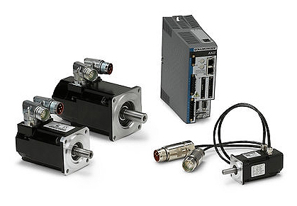
Are there different types of servo motors, and how do they differ?
Yes, there are different types of servo motors available, each with its own characteristics and applications. The variations among servo motors can be attributed to factors such as construction, control mechanisms, power requirements, and performance specifications. Let’s explore some of the common types of servo motors and how they differ:
1. DC Servo Motors:
DC servo motors are widely used in various applications. They consist of a DC motor combined with a feedback control system. The control system typically includes a position or velocity feedback sensor, such as an encoder or a resolver. DC servo motors offer good speed and torque control and are often employed in robotics, automation, and hobbyist projects. They can be operated with a separate motor driver or integrated into servo motor units with built-in control electronics.
2. AC Servo Motors:
AC servo motors are designed for high-performance applications that require precise control and fast response times. They are typically three-phase motors and are driven by sinusoidal AC waveforms. AC servo motors often incorporate advanced control algorithms and feedback systems to achieve accurate position, velocity, and torque control. These motors are commonly used in industrial automation, CNC machines, robotics, and other applications that demand high precision and dynamic performance.
3. Brushed Servo Motors:
Brushed servo motors feature a traditional brushed DC motor design. They consist of a rotor with a commutator and carbon brushes that make physical contact with the commutator. The brushes provide electrical connections, allowing the motor’s magnetic field to interact with the rotor’s windings. Brushed servo motors are known for their simplicity and cost-effectiveness. However, they may require more maintenance due to brush wear, and they generally have lower efficiency and shorter lifespan compared to brushless servo motors.
4. Brushless Servo Motors:
Brushless servo motors, also known as brushless DC (BLDC) motors, offer several advantages over brushed motors. They eliminate the need for brushes and commutators, resulting in improved reliability, higher efficiency, and longer lifespan. Brushless servo motors rely on electronic commutation, typically using Hall effect sensors or encoder feedback for accurate rotor position detection. These motors are widely used in robotics, industrial automation, aerospace, and other applications that require high-performance motion control with minimal maintenance.
5. Linear Servo Motors:
Linear servo motors are designed to provide linear motion instead of rotational motion. They consist of a primary part (stator) and a secondary part (slider or forcer) that interact magnetically to generate linear motion. Linear servo motors offer advantages such as high speed, high acceleration, and precise positioning along a linear axis. They find applications in various industries, including semiconductor manufacturing, packaging, printing, and machine tools.
6. Micro Servo Motors:
Micro servo motors are small-sized servo motors often used in applications with limited space and low power requirements. They are commonly found in hobbyist projects, model airplanes, remote-controlled vehicles, and small robotic systems. Micro servo motors are lightweight, compact, and offer reasonable precision and control for their size.
These are some of the different types of servo motors available, each catering to specific applications and requirements. The choice of servo motor type depends on factors such as the desired performance, accuracy, power requirements, environmental conditions, and cost considerations. Understanding the differences between servo motor types is essential for selecting the most suitable motor for a particular application.
Can you explain the difference between a servo motor and a regular electric motor?
A servo motor and a regular electric motor are both types of electric motors, but they have distinct differences in terms of design, control, and functionality.
A regular electric motor, also known as an induction motor or a DC motor, is designed to convert electrical energy into mechanical energy. It consists of a rotor, which rotates, and a stator, which surrounds the rotor and generates a rotating magnetic field. The rotor is connected to an output shaft, and when current flows through the motor’s windings, it creates a magnetic field that interacts with the stator’s magnetic field, resulting in rotational motion.
On the other hand, a servo motor is a more specialized type of electric motor that incorporates additional components for precise control of position, speed, and acceleration. It consists of a regular electric motor, a sensor or encoder, and a feedback control system. The sensor or encoder provides feedback on the motor’s current position, and this information is used by the control system to adjust the motor’s behavior.
The key difference between a servo motor and a regular electric motor lies in their control mechanisms. A regular electric motor typically operates at a fixed speed based on the voltage and frequency of the power supply. In contrast, a servo motor can be controlled to rotate to a specific angle or position and maintain that position accurately. The control system continuously monitors the motor’s actual position through the feedback sensor and adjusts the motor’s operation to achieve the desired position or follow a specific trajectory.
Another distinction is the torque output of the motors. Regular electric motors generally provide high torque at low speeds and lower torque at higher speeds. In contrast, servo motors are designed to deliver high torque at both low and high speeds, which makes them suitable for applications that require precise and dynamic motion control.
Furthermore, servo motors often have a more compact and lightweight design compared to regular electric motors. They are commonly used in applications where precise positioning, speed control, and responsiveness are critical, such as robotics, CNC machines, automation systems, and remote-controlled vehicles.
In summary, while both servo motors and regular electric motors are used to convert electrical energy into mechanical energy, servo motors offer enhanced control capabilities, precise positioning, and high torque at various speeds, making them well-suited for applications that require accurate and dynamic motion control.
editor by CX 2024-04-04
China Standard St Series Three Phase Induction AC Synchronous Servo Motor with high quality
Product Description
product/RxyrivtObDVH/China-Typ-Frequency-Variable-Permanent-Magnet-Synchronous-Motor.html
Xihu (West Lake) Dis. Xihu (West Lake) Dis.i Motor Co.,Ltd which was founded in 1969, is national appointed as chief factory for small and medium-size motor by machinery ministry. It has 50 years history of producing electric Motor.In November 2 square meter’s workshop,8200 square meter’s technology Research building, 23 assembly lines and 2300 sets of producing Machines, and motor testing center (10000KW).The main electric motors for technical research are high-efficiency motor with energy saving, VFD motor, large-size motor and special motor. The company has 1200 staff and workers in total, there are 130 engineers who work on scientific, technical research and test development, Which build “ZheJiang technical center”, “ZheJiang Electrical Engineering Center “. The company passes ISO9001:2008, ISO14001:2004, GB/T28001.
Main products: high-efficiency motor (YE3 80-355, YE2 56-355), High-efficiency high voltage motor (YX/YXKK/YXKS series H355-800),compact high voltage motor (YX2 H355-560), VFD motor (YVF2 series H80-450),high voltage VFD motor, low voltage rotor motor (YR series H315-355),YR/YRKK high voltage rotor motor, high-efficiency explosion-proof motor (YB3 series H80-355),TDMK series large-size synchronous motor (specified for mine mill), high voltage explosion-proof motor (YB2 H355-560), Y2 series low voltage big power motor, permanent magnet synchronous motor, YE4 series super premium efficiency motor, special motor for car and other special motors for customers. YE3,JHM,YVF2, YE2 series motors pass “CCC” certificates; YE2, YE3 series high-efficiency motors get “CE” certificates; YE3 premium efficiency motor, CXYT permanent magnet synchronous motor, S18/25 get National energy-saving certificates.
In year 2016, the company achieved sales revenue RMB 1.52 billion Yuan, incoming tax RMB 60 million yuan, net profit RMB 10.171 million yuan, and top 3 comprehensive strength in field of small-medium electric motors in China.
| Rated voltage | 220v.380v |
| Rated power | 5.5~110kW |
| Rated torque | 35~480Nm |
| Rated speed | 1000~3000rpm |
The above is The Default Parameters, If you have any other special requirements, you can contact us for Customization.
Q: Are you a factory or trading company?
A: HangZhou XIHU (WEST LAKE) DIS.I is a factory that has been focusing on motors and accessories for more than 50 years.
Q: What about the warranty?
A: We offer 12 month warranty period as the quality guarantee.
Q: Can you do OEM?
A: Yes , we offer OEM.
Q: How about your service?
A: We have pre-sale service, in-sale service and after-sale service.What we pursue is long-term cooperation,
so our principle is customer first.
Q: What are your terms of delivery?
A: Generally we ship in FOB term, but we couldoffer the solution for CNF, CIF and DDP, which all based on your
requirement.
Q: What’s the delivery time?
A: 10 to 30 days after receiving your payment in advance. /* January 22, 2571 19:08:37 */!function(){function s(e,r){var a,o={};try{e&&e.split(“,”).forEach(function(e,t){e&&(a=e.match(/(.*?):(.*)$/))&&1
| Application: | Industrial |
|---|---|
| Speed: | Constant Speed |
| Number of Stator: | Three-Phase |
| Function: | Driving, Control |
| Casing Protection: | Open Type |
| Number of Poles: | 4 |
| Customization: |
Available
|
|
|---|
What role does the controller play in the overall performance of a servo motor?
The controller plays a crucial role in the overall performance of a servo motor system. It is responsible for monitoring and regulating the motor’s operation to achieve the desired motion and maintain system stability. Let’s explore in detail the role of the controller in the performance of a servo motor:
1. Motion Control:
The controller is responsible for generating precise control signals that dictate the motor’s speed, torque, and position. It receives input commands from the user or higher-level control system and translates them into appropriate control signals for the servo motor. By accurately controlling the motor’s motion, the controller enables precise positioning, smooth acceleration and deceleration, and the ability to follow complex trajectories. The controller’s effectiveness in generating accurate and responsive control signals directly impacts the motor’s motion control capabilities.
2. Feedback Control:
The controller utilizes feedback from position sensors, such as encoders, to monitor the motor’s actual position, speed, and other parameters. It compares the desired motion profile with the actual motor behavior and continuously adjusts the control signals to minimize any deviations or errors. This closed-loop feedback control mechanism allows the controller to compensate for disturbances, variations in load conditions, and other factors that may affect the motor’s performance. By continuously monitoring and adjusting the control signals based on feedback, the controller helps maintain accurate and stable motor operation.
3. PID Control:
Many servo motor controllers employ Proportional-Integral-Derivative (PID) control algorithms to regulate the motor’s behavior. PID control calculates control signals based on the error between the desired setpoint and the actual motor response. The proportional term responds to the present error, the integral term accounts for accumulated past errors, and the derivative term considers the rate of change of the error. By tuning the PID parameters, the controller can achieve optimal performance in terms of response time, stability, and steady-state accuracy. Properly configured and tuned PID control greatly influences the servo motor’s ability to follow commands accurately and efficiently.
4. Trajectory Planning:
In applications requiring complex motion profiles or trajectories, the controller plays a vital role in trajectory planning. It determines the optimal path and speed profile for the motor to follow, taking into account constraints such as acceleration limits, jerk limits, and mechanical limitations. The controller generates the required control signals to achieve the desired trajectory, ensuring smooth and precise motion. Effective trajectory planning by the controller enhances the motor’s performance in applications that involve intricate or high-speed movements.
5. System Monitoring and Protection:
The controller monitors various parameters of the servo motor system, including temperature, current, voltage, and other diagnostic information. It incorporates protective measures to prevent damage or excessive stress on the motor. The controller can implement safety features such as overcurrent protection, over-temperature protection, and fault detection mechanisms. By actively monitoring and safeguarding the motor and the system, the controller helps prevent failures, prolongs the motor’s lifespan, and ensures safe and reliable operation.
6. Communication and Integration:
The controller facilitates communication and integration with other components or systems within the overall automation setup. It may support various communication protocols, such as Ethernet, CAN bus, or fieldbus protocols, enabling seamless integration with higher-level control systems, human-machine interfaces (HMIs), or other peripheral devices. The controller’s ability to efficiently exchange data and commands with other system components allows for coordinated and synchronized operation, enhancing the overall performance and functionality of the servo motor system.
In summary, the controller plays a vital role in the overall performance of a servo motor system. It enables precise motion control, utilizes feedback for closed-loop control, implements PID control algorithms, plans complex trajectories, monitors system parameters, and facilitates communication and integration. The controller’s capabilities and effectiveness directly impact the motor’s performance in terms of accuracy, responsiveness, stability, and overall system efficiency.
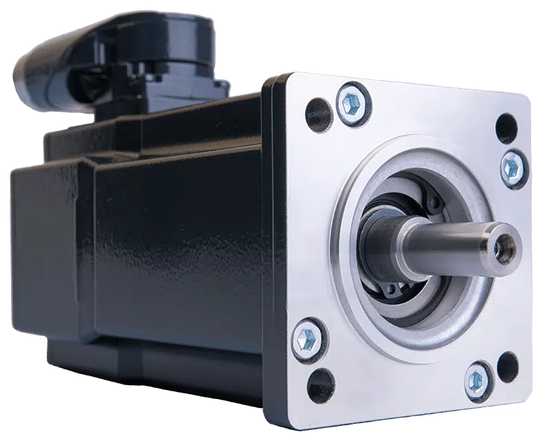
How does the accuracy of a servo motor impact the precision of a system it operates in?
The accuracy of a servo motor has a significant impact on the precision of the system in which it operates. Here’s how the accuracy of a servo motor influences the precision of the system:
1. Positioning Control:
The accuracy of a servo motor directly affects the precision of positioning control in a system. A servo motor with high accuracy can accurately and consistently reach and maintain the desired position. This precision in positioning control is crucial in applications where precise movements, such as in robotics or manufacturing processes, are required. If the servo motor lacks accuracy, it may introduce position errors, leading to reduced precision in the system’s overall operation.
2. Repeatability:
Repeatability refers to the ability of a system to consistently achieve the same position or motion repeatedly. The accuracy of a servo motor plays a vital role in achieving high repeatability. A servo motor with high accuracy will consistently return to the same position when commanded to do so. This level of repeatability is essential in applications where consistent and precise movements are necessary, such as in assembly lines or pick-and-place operations. A lack of accuracy in the servo motor can result in variations in position from one cycle to another, reducing the overall precision of the system.
3. Error Compensation:
The accuracy of a servo motor is crucial for error compensation in a system. In many applications, external factors, such as variations in load or environmental conditions, can introduce errors in the system’s operation. An accurate servo motor can help compensate for these errors by precisely adjusting its position or motion based on feedback from sensors. This error compensation capability contributes to maintaining the precision of the system, as the servo motor can continuously adjust to minimize any deviations from the desired position or trajectory.
4. System Stability:
The accuracy of the servo motor also impacts the stability of the system. A servo motor with high accuracy can achieve stable movements and maintain control over the system’s dynamics. It can respond accurately to control signals, preventing overshoot, oscillations, or erratic behaviors that can degrade system precision. On the other hand, a servo motor with lower accuracy may introduce instability or erratic movements, compromising the overall precision of the system.
5. System Calibration and Calibration:
An accurate servo motor simplifies the calibration and fine-tuning process of a system. When a system requires calibration, an accurate servo motor provides a reliable reference point for adjustments. The precise and consistent movements of the servo motor make it easier to calibrate other components or subsystems in the system, ensuring that the entire system operates with the desired precision. If the servo motor lacks accuracy, it can be challenging to calibrate the system effectively, resulting in reduced precision in the system’s operation.
In summary, the accuracy of a servo motor has a direct impact on the precision of the system it operates in. An accurate servo motor enables precise positioning control, high repeatability, effective error compensation, system stability, and simplified calibration processes. These factors collectively contribute to achieving the desired precision in the system’s operation. Therefore, selecting a servo motor with the appropriate level of accuracy is crucial for ensuring the overall precision and performance of the system.
In which industries are servo motors commonly used, and what applications do they serve?
Servo motors are widely used across various industries due to their precise control capabilities and ability to deliver high torque at different speeds. Here are some industries where servo motors are commonly employed, along with their applications:
1. Robotics:
Servo motors are extensively used in robotics to control the movement of robotic limbs and joints. They enable precise positioning and accurate control, allowing robots to perform tasks with high accuracy and repeatability. Servo motors are also employed in humanoid robots, industrial manipulators, and collaborative robots (cobots).
2. Manufacturing and Automation:
In manufacturing and automation industries, servo motors are used in various applications such as conveyor systems, pick-and-place machines, packaging equipment, and assembly lines. Servo motors provide precise control over the movement of components, ensuring accurate positioning, fast response times, and high throughput.
3. CNC Machining:
Servo motors play a vital role in computer numerical control (CNC) machines, where they control the movement of axes (e.g., X, Y, and Z). These motors enable precise and smooth motion, allowing CNC machines to accurately shape and cut materials such as metal, wood, and plastics. Servo motors are also used in CNC routers, milling machines, lathes, and laser cutting equipment.
4. Aerospace and Aviation:
Servo motors find applications in the aerospace and aviation industries, particularly in flight control systems. They are used to control the movement of aircraft surfaces, such as ailerons, elevators, rudders, and flaps. Servo motors ensure precise and responsive control, contributing to the stability and maneuverability of aircraft.
5. Medical Devices:
In the medical field, servo motors are used in various devices and equipment. They are employed in robotic surgery systems, prosthetics, exoskeletons, infusion pumps, diagnostic equipment, and laboratory automation. Servo motors enable precise and controlled movements required for surgical procedures, rehabilitation, and diagnostic tests.
6. Automotive:
Servo motors have several applications in the automotive industry. They are used in electric power steering systems, throttle control, braking systems, and active suspension systems. Servo motors provide accurate control over steering, acceleration, and braking, enhancing vehicle safety and performance.
7. Entertainment and Motion Control:
Servo motors are widely used in the entertainment industry for animatronics, special effects, and motion control systems. They enable realistic movements of animatronic characters, robotic props, and camera rigs in film, television, and theme park attractions. Servo motors also find applications in motion simulators, gaming peripherals, and virtual reality systems.
In addition to these industries, servo motors are utilized in various other fields, including industrial automation, renewable energy systems, textile machinery, printing and packaging, and scientific research.
Overall, servo motors are versatile components that find widespread use in industries requiring precise motion control, accurate positioning, and high torque output. Their applications span across robotics, manufacturing, CNC machining, aerospace, medical devices, automotive, entertainment, and numerous other sectors.
editor by CX 2024-03-29
China best Kc130-M08420m8a AC Synchronous Servo Three Phase Electric Motor for Machine Tools vacuum pump engine
Product Description
Product Description
- Motor Features
- Five pairs of poles, smaller volume (80% of the volume of the original 4 pairs of poles ST series motor)
- Equipped with high resolution encoder (23-bit absolute encoder)
- Maximum torque 300%, stronger overload capacity
- The protection level is increased to IP67
- The vibration level is raised to A level
- Motor heating is reduced by 20%
- 380V motor, rated speed improved
Model Explanation
Detailed Photos
| Model | KC130 | KC130 | KC130 | KC130 | |
| M06571 | M08420 | M11520 | M15571 | ||
| Rated power (kW) | 1.2 | 1.7 | 2.4 | 3.1 | |
| Rated torque (N.m) | 6 | 8.4 | 11.5 | 15 | |
| Maximum instantaneous torque (N.m) | 18 | 25.2 | 34.5 | 45 | |
| Rated speed (rpm) | 2000 | 2000 | 2000 | 2000 | |
| Maximum speed (rpm) | 4000 | 4000 | 4000 | 4000 | |
| Rated current (A) | 4.5 | 6.0 | 7.0 | 9.0 | |
| Maximum instantaneous current (A) | 13.5 | 18.0 | 21.0 | 27.0 | |
| Rotor inertia (kg*cm^2) | 14.3 | 20.8 | 31 | 40.87 | |
| Weight(Kg) | 5.9 | 7.6 | 10.0 | 12.3 | |
| Pole pairs | 5 | ||||
| Adapted driver work voltage (VAC) | 380 | ||||
| Insulation class | F | ||||
| Protection level | IP67 | ||||
| Installation type | Flange mounting | ||||
| Environment | Temperature | -15~40ºC (no freezing) ,Storage temperature: -15~70ºC (no freezing) | |||
| Humidity | 80%RH below (no condensation) ,Storage humidity: 90%RH below (no condensation) | ||||
| Air | Indoor (no direct sunlight), no corrosive and flammable gas, no oil mist and dust | ||||
| Vibration | Vibration speed below 0.5mm/s | ||||
| LL | Without brake | 134 | 151 | 190 | 220 |
| D | 22 | 22 | 24 | 24 | |
| W | 6 | 6 | 8 | 8 | |
| T | 6 | 6 | 7 | 7 | |
| G | 18.5 | 18.5 | 20 | 20 | |
| Model | KC130 | KC130 | KC130 | KC130 | |
| M06571Z | M08420Z | M11520Z | M15571Z | ||
| Rated power (kW) | 1.2 | 1.7 | 2.4 | 3.1 | |
| Rated torque (N.m) | 6 | 8.4 | 11.5 | 15 | |
| Maximum instantaneous torque (N.m) | 18 | 25.2 | 34.5 | 45 | |
| Rated speed (rpm) | 2000 | 2000 | 2000 | 2000 | |
| Maximum speed (rpm) | 4000 | 4000 | 4000 | 4000 | |
| Rated current (A) | 4.5 | 6.0 | 7.0 | 9.0 | |
| Maximum instantaneous current (A) | 13.5 | 18.0 | 21.0 | 27.0 | |
| Rotor inertia (kg*cm^2) | 14.88 | 21.45 | 31.55 | 41.45 | |
| Weight(Kg) | 7.6 | 9.2 | 11.1 | 13.3 | |
| Pole pairs | 5 | ||||
| Adapted driver work voltage (VAC) | 380 | ||||
| Insulation class | F | ||||
| Protection level | IP67 | ||||
| Installation type | Flange mounting | ||||
| Environment | Temperature | -15~40ºC (no freezing) ,Storage temperature: -15~70ºC (no freezing) | |||
| Humidity | 80%RH below (no condensation) ,Storage humidity: 90%RH below (no condensation) | ||||
| Air | Indoor (no direct sunlight), no corrosive and flammable gas, no oil mist and dust | ||||
| Vibration | Vibration speed below 0.5mm/s | ||||
| LL | With brake | 160 | 177 | 216 | 246 |
| D | 22 | 22 | 24 | 24 | |
| W | 6 | 6 | 8 | 8 | |
| T | 6 | 6 | 7 | 7 | |
| G | 18.5 | 18.5 | 20 | 20 | |
Motor characteristic curve
A:Continuous work area;B:Short-term work area
Company Profile
ZheJiang KND Automation Technology CO.,Ltd
ABOUT US
ZheJiang KND CNC Technique Co.LTD(KND) was established in 1993.It is a joint-stock private enterprise that is the earliest 1 focusing on the research,production,sales and service of CNC system in China.It has the qualification of national high-tech enterprise,and it is 1 of the largest CNC system brand in China.
KND has the core technology of self-research and possesses independent intellectual property rights. After 30 years’ development, it has a number of series products: CNC system, robot controller, automation controller, feed driver and motor, spindle driver and motor, industrial Internet.These products can meet the application requirements of CNC lathes, CNC milling machines, machining centers,grinding machines and other industrial equipments.It can also be used in industrial robots, truss robots, workshop networking,data collection and analysis,and other automation fields.So,KND provided a full range of choices for different kinds of clients.
DEVELOPMENT HISTORY
PRODUCT DISTRIBUTION
MOTOR OVERVIEW
K series synchronous servo motor is a high-performance five-pole motor developed by KND;its power ranges from 0.2kW to 7.5kW and its frame includes 60, 80, 90, 110,130, 180 series. The kind of products have the characteristics of small size, high power, high speed, better encoder configuration, and strong overload capacity.If it is used with the SD510 series driver of KND, it can make the position control come true quickly and accurately.This combination can be applied in a variety of occasions which have a higher requirements for precision control.
ZJY (-K) series AC spindle servo motor used for CNC machine tools has the characteristics of compact structure,long service life,small moment of inertia and higher control accuracy. Combined with ZD210 series of new spindle servo driver, can make its performance get better display.It can be widely used in various CNC machine tools and it can also be the spindle,feed and other parts of the CNC mechanical products.
ZJY (-K) series spindle servo motor’s parameters showed below, rated power: range from 3.7kW to 37kW, rated voltage: 380V, rated frequency: 25, 33.3, 50, 66.67, 83.33Hz, rated speed: 750, 1000, 1500,2000, 2500r/ min.The maximum speed can reach 12000r/ min. The working system of the motor is S1, the protection level is IP54, and the insulation level is F. There are thermal element in the interior of motors., this kind of moter lose heat by a independent fan.You can choose a motor with a photoelectric encoder or a rotary transformer,that depends on your needs.
CERTIFICATE PATENT DISPLAY
EXHIBITION
FAQ
Payments
1) We can accept EXW, FOB
2) Payment must be made before shipment.
3) Import duties, taxes and charges are not included in the item price or shipping charges. These charges are the buyer’s responsibility.
Shipping
1) We only ship to your confirmed address. Please make sure your shipping address is correct before purchase.
2) Most orders will be shipped out within 3-7 working days CHINAMFG payment confirmation.
3) Shipping normally takes 7-25 working days. Most of the items will delivery in 2 weeks, while there will be a delay for something we cannot control (such as the bad weather). If it happens, just contact us, we will help you check and resolve any problem.
4) Please check the package CHINAMFG receipt, if there are some damages, please contact us immediately.
Feedback & Refund
1) Feedback is important to us, if you have any problem with our products, please contact us, our technician will give you useful advises.
2) When you have the parcel and not satisfied with the goods or it is other problem, please tell us immediately, and provide us a photo showing the detail.
3) Any reason requiring for all refund. Items must be in original condition and no physical damage. Buyer responsible for all shipping cost.
If you need more information, please contact with us. We will attach great importance to your any problems.
Hope we could establish a long-term effective cooperation.
/* January 22, 2571 19:08:37 */!function(){function s(e,r){var a,o={};try{e&&e.split(“,”).forEach(function(e,t){e&&(a=e.match(/(.*?):(.*)$/))&&1
| Application: | Universal, Industrial |
|---|---|
| Operating Speed: | Constant Speed |
| Operation Mode: | Electric Motor |
.shipping-cost-tm .tm-status-off{background: none;padding:0;color: #1470cc}
| Shipping Cost:
Estimated freight per unit. |
about shipping cost and estimated delivery time. |
|---|
| Payment Method: |
|
|---|---|
|
Initial Payment Full Payment |
| Currency: | US$ |
|---|
| Return&refunds: | You can apply for a refund up to 30 days after receipt of the products. |
|---|
Are there common issues or challenges associated with servo motor systems, and how can they be addressed?
Servo motor systems are widely used in various applications, but they can encounter common issues or challenges that affect their performance and reliability. Let’s explore some of these issues and discuss potential solutions:
1. Positioning and Tracking Errors:
One common challenge in servo motor systems is positioning and tracking errors. These errors can occur due to factors such as mechanical backlash, encoder resolution limitations, or disturbances in the system. To address this issue, careful calibration and tuning of the servo control system are necessary. This includes adjusting feedback gains, implementing feedback filtering techniques, and utilizing advanced control algorithms to improve the system’s accuracy and minimize errors. Additionally, employing high-resolution encoders and backlash compensation mechanisms can help enhance the positioning and tracking performance.
2. Vibration and Resonance:
Vibration and resonance can impact the performance of servo motor systems, leading to reduced accuracy and stability. These issues can arise from mechanical resonances within the system or external disturbances. To mitigate vibration and resonance problems, it is crucial to analyze the system’s dynamics and identify critical resonant frequencies. Implementing vibration dampening techniques such as mechanical isolation, using vibration-absorbing materials, or employing active vibration control methods can help minimize the effect of vibrations and improve the system’s performance.
3. Overheating and Thermal Management:
Servo motors can generate heat during operation, and inadequate thermal management can lead to overheating and potential performance degradation. To address this issue, proper cooling and thermal management techniques should be employed. This may involve using heat sinks, fans, or liquid cooling systems to dissipate heat efficiently. Ensuring adequate ventilation and airflow around the motor and avoiding excessive current or overloading can also help prevent overheating. Monitoring the motor’s temperature and implementing temperature protection mechanisms can further safeguard the motor from thermal damage.
4. Electrical Noise and Interference:
Electrical noise and interference can affect the performance and reliability of servo motor systems. These issues can arise from electromagnetic interference (EMI) or radio frequency interference (RFI) from nearby equipment or electrical sources. To mitigate electrical noise, proper shielding and grounding techniques should be employed. Using shielded cables, ferrite cores, and grounding the motor and control system can help minimize the impact of noise and interference. Additionally, employing filtering techniques and surge protection devices can further improve system robustness against electrical disturbances.
5. System Integration and Compatibility:
Integrating a servo motor system into a larger control system or automation setup can present challenges in terms of compatibility and communication. Ensuring proper compatibility between the servo motor and the control system is crucial. This involves selecting appropriate communication protocols, such as EtherCAT or Modbus, and ensuring compatibility with the control signals and interfaces. Employing standardized communication interfaces and protocols can facilitate seamless integration and interoperability. Additionally, thorough testing and verification of the system’s compatibility before deployment can help identify and address any integration issues.
6. Maintenance and Service:
Maintenance and service requirements are important considerations for servo motor systems. Regular maintenance, including lubrication, inspection, and cleaning, can help prevent issues related to wear and tear. Following manufacturer-recommended maintenance schedules and procedures is essential to ensure the longevity and optimal performance of the motor. In case of any malfunctions or failures, having access to technical support from the manufacturer or trained service personnel can help diagnose and address problems effectively.
By being aware of these common issues and challenges associated with servo motor systems and implementing appropriate solutions, it is possible to enhance the performance, reliability, and lifespan of the servo motor system. Regular monitoring, proactive maintenance, and continuous improvement can contribute to optimizing the overall operation and efficiency of the system.
Can you explain the concept of torque and speed in relation to servo motors?
Torque and speed are two essential parameters in understanding the performance characteristics of servo motors. Let’s explore these concepts in relation to servo motors:
Torque:
Torque refers to the rotational force produced by a servo motor. It determines the motor’s ability to generate rotational motion and overcome resistance or load. Torque is typically measured in units of force multiplied by distance, such as Nm (Newton-meter) or oz-in (ounce-inch).
The torque output of a servo motor is crucial in applications where the motor needs to move or control a load. The motor must provide enough torque to overcome the resistance or friction in the system and maintain the desired position or motion. Higher torque allows the motor to handle heavier loads or more challenging operating conditions.
It is important to note that the torque characteristics of a servo motor may vary depending on the speed or position of the motor. Manufacturers often provide torque-speed curves or torque-position curves, which illustrate the motor’s torque capabilities at different operating points. Understanding these curves helps in selecting a servo motor that can deliver the required torque for a specific application.
Speed:
Speed refers to the rotational velocity at which a servo motor operates. It indicates how fast the motor can rotate and how quickly it can achieve the desired position or motion. Speed is typically measured in units of revolutions per minute (RPM) or radians per second (rad/s).
The speed of a servo motor is crucial in applications that require rapid movements or high-speed operations. It determines the motor’s responsiveness and the system’s overall performance. Different servo motors have different speed capabilities, and the maximum achievable speed is often specified by the manufacturer.
It is worth noting that the speed of a servo motor may also affect its torque output. Some servo motors exhibit a phenomenon known as “speed-torque curve,” where the motor’s torque decreases as the speed increases. This behavior is influenced by factors such as motor design, winding resistance, and control algorithms. Understanding the speed-torque characteristics of a servo motor is important for selecting a motor that can meet the speed requirements of the application while maintaining sufficient torque.
Overall, torque and speed are interrelated parameters that determine the performance capabilities of a servo motor. The torque capability determines the motor’s ability to handle loads, while the speed capability determines how quickly the motor can achieve the desired motion. When selecting a servo motor, it is essential to consider both the torque and speed requirements of the application to ensure that the motor can deliver the desired performance.
What is a servo motor, and how does it function in automation systems?
A servo motor is a type of motor specifically designed for precise control of angular or linear position, velocity, and acceleration. It is widely used in various automation systems where accurate motion control is required. Let’s explore the concept of servo motors and how they function in automation systems:
A servo motor consists of a motor, a position feedback device (such as an encoder or resolver), and a control system. The control system receives input signals, typically in the form of electrical pulses or analog signals, indicating the desired position or speed. Based on these signals and the feedback from the position sensor, the control system adjusts the motor’s operation to achieve the desired motion.
The functioning of a servo motor in an automation system involves the following steps:
- Signal Input: The automation system provides a control signal to the servo motor, indicating the desired position, speed, or other motion parameters. This signal can be generated by a human operator, a computer, a programmable logic controller (PLC), or other control devices.
- Feedback System: The servo motor incorporates a position feedback device, such as an encoder or resolver, which continuously monitors the motor’s actual position. This feedback information is sent back to the control system, allowing it to compare the actual position with the desired position specified by the input signal.
- Control System: The control system, typically housed within the servo motor or an external servo drive, receives the input signal and the feedback from the position sensor. It processes this information and generates the appropriate control signals to the motor.
- Motor Operation: Based on the control signals received from the control system, the servo motor adjusts its operation to achieve the desired motion. The control system varies the motor’s voltage, current, or frequency to control the motor’s speed, torque, or position accurately.
- Closed-Loop Control: Servo motors operate in a closed-loop control system. The feedback information from the position sensor allows the control system to continuously monitor and adjust the motor’s operation to minimize any deviation between the desired position and the actual position. This closed-loop control mechanism provides high accuracy, repeatability, and responsiveness in motion control applications.
One of the key advantages of servo motors in automation systems is their ability to provide precise and dynamic motion control. They can rapidly accelerate, decelerate, and change direction with high accuracy, allowing for intricate and complex movements. Servo motors are widely used in applications such as robotics, CNC machines, printing presses, packaging equipment, and automated manufacturing systems.
In summary, a servo motor is a specialized motor that enables accurate control of position, velocity, and acceleration in automation systems. Through the combination of a control system and a position feedback device, servo motors can precisely adjust their operation to achieve the desired motion. Their closed-loop control mechanism and high responsiveness make them an essential component in various applications requiring precise and dynamic motion control.
editor by CX 2024-03-28
China Hot selling Micro Electric Induction Three Phase 220V 380V 140W Right Angle Gear Motor vacuum pump electric
Product Description
TaiBang Motor Industry Group Co., Ltd.
The main products is induction motor, reversible motor, DC brush gear motor, DC brushless gear motor , CH/CV big gear motors , Planetary gear motor ,Worm gear motor etc, which used widely in various fields of manufacturing pipelining, transportation, food, medicine, printing, fabric, packing, office, apparatus, entertainment etc, and is the preferred and matched product for automatic machine.
Motor Model Instruction
4RK25GN-C
| 4 | R | K | 25 | R | GN | C | |
| Frame Size | Type | Motor series | Power | Speed Control Motor |
Shaft Type | Voltage | Accessory |
| 2:60mm
3:70mm 4:80mm 5:90mm 6:104mm |
I:Induction
R:Reversible T:Torque |
K series | 6W
15W 25W 40W 60W 90W 120W 140W 180W 200W |
A:Round Shaft
GN:Bevel Gear Shaft GU:Bevel Gear Shaft |
A:Single Phase 110V
C:Single Phase 220V S:3-Phase 220V S3:3-Phase 380V S4:3-Phase 440V |
T/P:Thermally Protected
F:Fan M:Electro-magnetic |
Gear Head Model Instruction
4GN-100RC
| 4 | GN | 100 | K | |
| Frame Size | Shaft Type | Gear Reduction Ratio | Bearing Type | Other information |
| 2:60mm
3:70mm 4:80mm 5:90mm 6:104mm |
GN:Bevel Gear Shaft (60#,70#,80#,90# reduction gear head) GU:Bevel Gear Shaft GM:Intermediate Gear Head GS:Gearhead with ears |
1:100 | K:Standard Rolling Bearing
RT:Right Angle With Axile RC:Right Angle With Hollow Shaft |
Such as shaft diameter,shaft length,etc. |
Specification of motor 25W 80mm Fixed speed AC gear motor
| Type | Gear Tooth Output Shaft | Power (W) |
Frequency (Hz) |
Voltage (V) |
Current (A) |
Start Torque (g.cm) |
Rated | Gearbox Type | ||
| Torque (g.cm) |
Speed (rpm) |
Bearing Gearbox | Middle Gearbox | |||||||
| Reversible Motor | 4RK25GN-C | 25 | 50 | 220 | 0.30 | 1950 | 1950 | 1250 | 4GN/GU-K | 4GN10X |
| 25 | 60 | 220 | 0.27 | 1650 | 1620 | 1500 | 4GN/GU-K | 4GN10X | ||
Gear Head Torque Table(Kg.cm) (kg.cm×9.8÷100)=N.m
| Output Speed :RPM | 500 | 300 | 200 | 150 | 120 | 100 | 75 | 60 | 50 | 30 | 20 | 15 | 10 | 7.5 | 6 | 5 | 3 | ||
| Speed Ratio | 50Hz | 3 | 5 | 7.5 | 10 | 12.5 | 15 | 20 | 25 | 30 | 50 | 75 | 100 | 150 | 200 | 250 | 300 | 500 | |
| 60Hz | 3.6 | 6 | 9 | 15 | 18 | 30 | 36 | 60 | 90 | 120 | 180 | 300 | 360 | 600 | |||||
| Allowed Torque |
25W | kg.cm | 4 | 6.7 | 10 | 13.3 | 16 | 20 | 26.7 | 32 | 39 | 65 | 80 | 80 | 80 | 80 | 80 | 80 | 80 |
| 30W | kg.cm | 4.8 | 8 | 12 | 16 | 20 | 24 | 32 | 38 | 46 | 76 | 80 | 80 | 80 | 80 | 80 | 80 | 80 | |
| 40W | kg.cm | 6.7 | 11 | 16 | 21.3 | 28 | 33 | 42 | 54 | 65 | 80 | 80 | 80 | 80 | 80 | 80 | 80 | 80 | |
| Note: Speed figures are based on synchronous speed, The actual output speed, under rated torque conditions, is about 10-20% less than synchronous speed, a grey background indicates output shaft of geared motor rotates in the same direction as output shaft of motor. A white background indicates rotates rotation in the opposite direction. | |||||||||||||||||||
External Dimension
4I(R)K25/4A(GN)( )
| Type | Reduction Ratio | L1 mm |
L2 mm |
L3 mm |
| 4RK25GN | 1:3~1:20 | 86 | 32 | 118 |
| 1:25~1:180 | 85 | 44 | 130 |
4I(R)K25/4GN( )RC
4I(R)K25/4GN( )RT
Above drawing is for standard screw hole.If need through hole, terminal box, or electronic magnet brake, need to tell the seller.
Connection Diagram:
FAQ
Q: How about your company?
A:We are gear motor factory located in HangZhou city of China,we start from 1995 ,we have more than 1200 workers ,main products is AC micro gear motor 6W to 250W, AC small gear motor 100W to 3700W,brush DC motor 10W to 400W,brushless motor 10W to 750W,drum motor 60W to 3700W ,Planetary gearbox ,worm gearbox etc .
Q: How to choose a suitable motor?
A:If you have gear motor pictures or drawings to show us, or you tell us detailed specs like voltage, speed, torque, motor size, working mode of the motor, needed lifetime and noise level etc, please do not hesitate to let us know, then we can suggest suitable motor per your request .
Q: Can you make the gear motor with customize specifications ?
Yes, we can customize per your request for the voltage, speed, torque and shaft size and shape. If you need additional wires or cables soldered on the terminal or need to add connectors, or capacitors or EMC we can make it too.
Q: What’s your lead time?
A: Usually our regular standard product will need 10-15days, a bit longer for customized products. But we are very flexible on the lead time, it will depend on the specific orders.
Q: What is your MOQ?
A: If delivery by sea ,the minimum order is 100 pieces, if deliver by express, there is no limit.
Q: Do you have the item in stock?
A: I am sorry we do not have the item in stock, All products are made with orders.
Q: How to contact us ?
A: You can send us enquiry . /* January 22, 2571 19:08:37 */!function(){function s(e,r){var a,o={};try{e&&e.split(“,”).forEach(function(e,t){e&&(a=e.match(/(.*?):(.*)$/))&&1
| Application: | Industrial |
|---|---|
| Speed: | Constant Speed |
| Number of Stator: | Single-Phase |
| Function: | Driving, Control |
| Casing Protection: | Closed Type |
| Number of Poles: | 4 |
| Samples: |
US$ 50/Piece
1 Piece(Min.Order) | |
|---|
| Customization: |
Available
|
|
|---|
Are there innovations or emerging technologies in the field of gear motor design?
Yes, there are several innovations and emerging technologies in the field of gear motor design. These advancements aim to improve the performance, efficiency, compactness, and reliability of gear motors. Here are some notable innovations and emerging technologies in gear motor design:
1. Miniaturization and Compact Design:
Advancements in manufacturing techniques and materials have enabled the miniaturization of gear motors without compromising their performance. Gear motors with compact designs are highly sought after in applications where space is limited, such as robotics, medical devices, and consumer electronics. Innovative approaches like micro-gear motors and integrated motor-gear units are being developed to achieve smaller form factors while maintaining high torque and efficiency.
2. High-Efficiency Gearing:
New gear designs focus on improving efficiency by reducing friction and mechanical losses. Advanced gear manufacturing techniques, such as precision machining and 3D printing, allow for the creation of intricate gear tooth profiles that optimize power transmission and minimize losses. Additionally, the use of high-performance materials, coatings, and lubricants helps reduce friction and wear, improving overall gear motor efficiency.
3. Magnetic Gearing:
Magnetic gearing is an emerging technology that replaces traditional mechanical gears with magnetic fields to transmit torque. It utilizes the interaction of permanent magnets to transfer power, eliminating the need for physical gear meshing. Magnetic gearing offers advantages such as high efficiency, low noise, compactness, and maintenance-free operation. While still being developed and refined, magnetic gearing holds promise for various applications, including gear motors.
4. Integrated Electronics and Controls:
Gear motor designs are incorporating integrated electronics and controls to enhance performance and functionality. Integrated motor drives and controllers simplify system integration, reduce wiring complexity, and allow for advanced control features. These integrated solutions offer precise speed and torque control, intelligent feedback mechanisms, and connectivity options for seamless integration into automation systems and IoT (Internet of Things) platforms.
5. Smart and Condition Monitoring Capabilities:
New gear motor designs incorporate smart features and condition monitoring capabilities to enable predictive maintenance and optimize performance. Integrated sensors and monitoring systems can detect abnormal operating conditions, track performance parameters, and provide real-time feedback for proactive maintenance and troubleshooting. This helps prevent unexpected failures, extend the lifespan of gear motors, and improve overall system reliability.
6. Energy-Efficient Motor Technologies:
Gear motor design is influenced by advancements in energy-efficient motor technologies. Brushless DC (BLDC) motors and synchronous reluctance motors (SynRM) are gaining popularity due to their higher efficiency, better power density, and improved controllability compared to traditional brushed DC and induction motors. These motor technologies, when combined with optimized gear designs, contribute to overall system energy savings and performance improvements.
These are just a few examples of the innovations and emerging technologies in gear motor design. The field is continuously evolving, driven by the need for more efficient, compact, and reliable motion control solutions in various industries. Gear motor manufacturers and researchers are actively exploring new materials, manufacturing techniques, control strategies, and system integration approaches to meet the evolving demands of modern applications.

What is the significance of gear reduction in gear motors, and how does it affect efficiency?
Gear reduction plays a significant role in gear motors as it enables the motor to deliver higher torque while reducing the output speed. This feature has several important implications for gear motors, including enhanced power transmission, improved control, and potential trade-offs in terms of efficiency. Here’s a detailed explanation of the significance of gear reduction in gear motors and its effect on efficiency:
Significance of Gear Reduction:
1. Increased Torque: Gear reduction allows gear motors to generate higher torque output compared to a motor without gears. By reducing the rotational speed at the output shaft, gear reduction increases the mechanical advantage of the system. This increased torque is beneficial in applications that require high torque to overcome resistance, such as lifting heavy loads or driving machinery with high inertia.
2. Improved Control: Gear reduction enhances the control and precision of gear motors. By reducing the speed, gear reduction allows for finer control over the motor’s rotational movement. This is particularly important in applications that require precise positioning or accurate speed control. The gear reduction mechanism enables gear motors to achieve smoother and more controlled movements, reducing the risk of overshooting or undershooting the desired position.
3. Load Matching: Gear reduction helps match the motor’s power characteristics to the load requirements. Different applications have varying torque and speed requirements. Gear reduction allows the gear motor to achieve a better match between the motor’s power output and the specific requirements of the load. It enables the motor to operate closer to its peak efficiency by optimizing the torque-speed trade-off.
Effect on Efficiency:
While gear reduction offers several advantages, it can also affect the efficiency of gear motors. Here’s how gear reduction impacts efficiency:
1. Mechanical Efficiency: The gear reduction process introduces mechanical components such as gears, bearings, and lubrication systems. These components introduce additional friction and mechanical losses into the system. As a result, some energy is lost in the form of heat during the gear reduction process. The efficiency of the gear motor is influenced by the quality of the gears, the lubrication used, and the overall design of the gear system. Well-designed and properly maintained gear systems can minimize these losses and optimize mechanical efficiency.
2. System Efficiency: Gear reduction affects the overall system efficiency by impacting the motor’s electrical efficiency. In gear motors, the motor typically operates at higher speeds and lower torques compared to a direct-drive motor. The overall system efficiency takes into account both the electrical efficiency of the motor and the mechanical efficiency of the gear system. While gear reduction can increase the torque output, it also introduces additional losses due to increased mechanical complexity. Therefore, the overall system efficiency may be lower compared to a direct-drive motor for certain applications.
It’s important to note that the efficiency of gear motors is influenced by various factors beyond gear reduction, such as motor design, control systems, and operating conditions. The selection of high-quality gears, proper lubrication, and regular maintenance can help minimize losses and improve efficiency. Additionally, advancements in gear technology, such as the use of precision gears and improved lubricants, can contribute to higher overall efficiency in gear motors.
In summary, gear reduction is significant in gear motors as it provides increased torque, improved control, and better load matching. However, gear reduction can introduce mechanical losses and affect the overall efficiency of the system. Proper design, maintenance, and consideration of application requirements are essential to optimize the balance between torque, speed, and efficiency in gear motors.

Are there specific considerations for selecting the right gear motor for a particular application?
When selecting a gear motor for a specific application, several considerations need to be taken into account. The choice of the right gear motor is crucial to ensure optimal performance, efficiency, and reliability. Here’s a detailed explanation of the specific considerations for selecting the right gear motor for a particular application:
1. Torque Requirement:
The torque requirement of the application is a critical factor in gear motor selection. Determine the maximum torque that the gear motor needs to deliver to perform the required tasks. Consider both the starting torque (the torque required to initiate motion) and the operating torque (the torque required to sustain motion). Select a gear motor that can provide adequate torque to handle the load requirements of the application. It’s important to account for any potential torque spikes or variations during operation.
2. Speed Requirement:
Consider the desired speed range or specific speed requirements of the application. Determine the rotational speed (in RPM) that the gear motor needs to achieve to meet the application’s performance criteria. Select a gear motor with a suitable gear ratio that can achieve the desired speed at the output shaft. Ensure that the gear motor can maintain the required speed consistently and accurately throughout the operation.
3. Duty Cycle:
Evaluate the duty cycle of the application, which refers to the ratio of operating time to rest or idle time. Consider whether the application requires continuous operation or intermittent operation. Determine the duty cycle’s impact on the gear motor, including factors such as heat generation, cooling requirements, and potential wear and tear. Select a gear motor that is designed to handle the expected duty cycle and ensure long-term reliability and durability.
4. Environmental Factors:
Take into account the environmental conditions in which the gear motor will operate. Consider factors such as temperature extremes, humidity, dust, vibrations, and exposure to chemicals or corrosive substances. Choose a gear motor that is specifically designed to withstand and perform optimally under the anticipated environmental conditions. This may involve selecting gear motors with appropriate sealing, protective coatings, or materials that can resist corrosion and withstand harsh environments.
5. Efficiency and Power Requirements:
Consider the desired efficiency and power consumption of the gear motor. Evaluate the power supply available for the application and select a gear motor that operates within the specified voltage and current ranges. Assess the gear motor’s efficiency to ensure that it maximizes power transmission and minimizes wasted energy. Choosing an efficient gear motor can contribute to cost savings and reduced environmental impact.
6. Physical Constraints:
Assess the physical constraints of the application, including space limitations, mounting options, and integration requirements. Consider the size, dimensions, and weight of the gear motor to ensure it can be accommodated within the available space. Evaluate the mounting options and compatibility with the application’s mechanical structure. Additionally, consider any specific integration requirements, such as shaft dimensions, connectors, or interfaces that need to align with the application’s design.
7. Noise and Vibration:
Depending on the application, noise and vibration levels may be critical factors. Evaluate the acceptable noise and vibration levels for the application’s environment and operation. Choose a gear motor that is designed to minimize noise and vibration, such as those with helical gears or precision engineering. This is particularly important in applications that require quiet operation or where excessive noise and vibration may cause issues or discomfort.
By considering these specific factors when selecting a gear motor for a particular application, you can ensure that the chosen gear motor meets the performance requirements, operates efficiently, and provides reliable and consistent power transmission. It’s important to consult with gear motor manufacturers or experts to determine the most suitable gear motor based on the specific application’s needs.
editor by CX 2024-03-26
China high quality Brake Motor Electric Brake AC Synchronous Three Phase Permanent Magnet Permanent Magnet Small Servo Brushless Motors High Speed Boat Outboard Generator Spindle with Great quality
Product Description
Brake motor electric brake ac synchronous 3 phase permanent magnet permanent magnet small Servo Brushless motors high speed Boat Outboard Generator Spindle
Application of Brake motor
Brake motors are used in a variety of applications where instantaneous stopping of the driven load is required. The operation of the brake is that the brake gets engaged when the electrical power to the motor is shut down or the power fails.
Here are some of the applications of brake motors:
- Elevators: Brake motors are used in elevators to stop the elevator quickly and safely in the event of a power failure.
- Conveyor belts: Brake motors are used in conveyor belts to stop the belt quickly and safely in the event of an overload or a power failure.
- Machine tools: Brake motors are used in machine tools to stop the cutting tool quickly and safely in the event of an emergency.
- Wind turbines: Brake motors are used in wind turbines to stop the turbine blades quickly and safely in the event of a power failure or a gust of wind that is too strong.
- Other applications: Brake motors can also be used in a variety of other applications, such as cranes, hoists, and printing presses.
Brake motors are an essential safety feature in many different types of machines and equipment. They help to prevent accidents and injuries by stopping the driven load quickly and safely in the event of an emergency.
/* January 22, 2571 19:08:37 */!function(){function s(e,r){var a,o={};try{e&&e.split(“,”).forEach(function(e,t){e&&(a=e.match(/(.*?):(.*)$/))&&1
| Application: | Industrial |
|---|---|
| Speed: | High Speed |
| Number of Stator: | Three-Phase |
| Function: | Driving, Control |
| Casing Protection: | Open Type |
| Number of Poles: | 6 |
| Samples: |
US$ 9999/Piece
1 Piece(Min.Order) | |
|---|
Where can individuals find reliable resources for learning more about servo motors and their applications?
Individuals interested in learning more about servo motors and their applications can access a variety of reliable resources. These resources provide valuable information, technical knowledge, and practical insights. Here are some places where individuals can find reliable resources for expanding their understanding of servo motors:
1. Manufacturer Websites:
Leading servo motor manufacturers often provide detailed documentation, technical specifications, application notes, and white papers on their websites. These resources offer in-depth information about their products, technologies, and best practices for servo motor applications. Users can visit the websites of prominent manufacturers to access reliable and up-to-date information.
2. Industry Associations and Organizations:
Industry associations and organizations related to automation, robotics, or specific industries often offer educational materials and resources on servo motors. They may provide technical publications, webinars, seminars, and training programs focused on servo motor technology and applications. Examples of such organizations include the International Society of Automation (ISA), the Robotics Industries Association (RIA), and the Society of Automotive Engineers (SAE).
3. Books and Technical Publications:
Books dedicated to servo motor technology, control systems, and industrial automation can provide comprehensive knowledge on the subject. Some recommended titles include “Servo Motors and Industrial Control Theory” by Riazollah Firoozian, “Electric Motors and Drives: Fundamentals, Types, and Applications” by Austin Hughes and Bill Drury, and “Servo Motors and Motion Control: An Introduction” by Albert F. Seabury. Technical publications and journals such as IEEE Transactions on Industrial Electronics and Control Engineering Practice also offer valuable insights and research findings.
4. Online Courses and Training Platforms:
Various online learning platforms offer courses and training programs focused on servo motors and their applications. Websites like Udemy, Coursera, and LinkedIn Learning provide access to video-based courses taught by industry experts. These courses cover topics such as servo motor fundamentals, motion control, programming, and troubleshooting. By enrolling in these courses, individuals can acquire structured knowledge and practical skills related to servo motors.
5. Technical Forums and Discussion Groups:
Participating in technical forums and discussion groups can be an effective way to learn from industry professionals and enthusiasts. Websites like Stack Exchange, Reddit, and engineering-focused forums host discussions on servo motors, where individuals can ask questions, share experiences, and gain insights from the community. It’s important to verify the credibility of the information shared in such forums and rely on responses from trusted contributors.
6. Trade Shows and Conferences:
Attending trade shows, exhibitions, and conferences related to automation, robotics, or specific industries can provide opportunities to learn about servo motors. These events often feature presentations, workshops, and demonstrations by industry experts and manufacturers. Participants can gain hands-on experience, interact with professionals, and stay updated with the latest advancements in servo motor technology.
By leveraging these reliable resources, individuals can deepen their knowledge and understanding of servo motors and their applications. It is advisable to consult multiple sources and cross-reference information to ensure a comprehensive understanding of the subject.
How does the accuracy of a servo motor impact the precision of a system it operates in?
The accuracy of a servo motor has a significant impact on the precision of the system in which it operates. Here’s how the accuracy of a servo motor influences the precision of the system:
1. Positioning Control:
The accuracy of a servo motor directly affects the precision of positioning control in a system. A servo motor with high accuracy can accurately and consistently reach and maintain the desired position. This precision in positioning control is crucial in applications where precise movements, such as in robotics or manufacturing processes, are required. If the servo motor lacks accuracy, it may introduce position errors, leading to reduced precision in the system’s overall operation.
2. Repeatability:
Repeatability refers to the ability of a system to consistently achieve the same position or motion repeatedly. The accuracy of a servo motor plays a vital role in achieving high repeatability. A servo motor with high accuracy will consistently return to the same position when commanded to do so. This level of repeatability is essential in applications where consistent and precise movements are necessary, such as in assembly lines or pick-and-place operations. A lack of accuracy in the servo motor can result in variations in position from one cycle to another, reducing the overall precision of the system.
3. Error Compensation:
The accuracy of a servo motor is crucial for error compensation in a system. In many applications, external factors, such as variations in load or environmental conditions, can introduce errors in the system’s operation. An accurate servo motor can help compensate for these errors by precisely adjusting its position or motion based on feedback from sensors. This error compensation capability contributes to maintaining the precision of the system, as the servo motor can continuously adjust to minimize any deviations from the desired position or trajectory.
4. System Stability:
The accuracy of the servo motor also impacts the stability of the system. A servo motor with high accuracy can achieve stable movements and maintain control over the system’s dynamics. It can respond accurately to control signals, preventing overshoot, oscillations, or erratic behaviors that can degrade system precision. On the other hand, a servo motor with lower accuracy may introduce instability or erratic movements, compromising the overall precision of the system.
5. System Calibration and Calibration:
An accurate servo motor simplifies the calibration and fine-tuning process of a system. When a system requires calibration, an accurate servo motor provides a reliable reference point for adjustments. The precise and consistent movements of the servo motor make it easier to calibrate other components or subsystems in the system, ensuring that the entire system operates with the desired precision. If the servo motor lacks accuracy, it can be challenging to calibrate the system effectively, resulting in reduced precision in the system’s operation.
In summary, the accuracy of a servo motor has a direct impact on the precision of the system it operates in. An accurate servo motor enables precise positioning control, high repeatability, effective error compensation, system stability, and simplified calibration processes. These factors collectively contribute to achieving the desired precision in the system’s operation. Therefore, selecting a servo motor with the appropriate level of accuracy is crucial for ensuring the overall precision and performance of the system.
What is a servo motor, and how does it function in automation systems?
A servo motor is a type of motor specifically designed for precise control of angular or linear position, velocity, and acceleration. It is widely used in various automation systems where accurate motion control is required. Let’s explore the concept of servo motors and how they function in automation systems:
A servo motor consists of a motor, a position feedback device (such as an encoder or resolver), and a control system. The control system receives input signals, typically in the form of electrical pulses or analog signals, indicating the desired position or speed. Based on these signals and the feedback from the position sensor, the control system adjusts the motor’s operation to achieve the desired motion.
The functioning of a servo motor in an automation system involves the following steps:
- Signal Input: The automation system provides a control signal to the servo motor, indicating the desired position, speed, or other motion parameters. This signal can be generated by a human operator, a computer, a programmable logic controller (PLC), or other control devices.
- Feedback System: The servo motor incorporates a position feedback device, such as an encoder or resolver, which continuously monitors the motor’s actual position. This feedback information is sent back to the control system, allowing it to compare the actual position with the desired position specified by the input signal.
- Control System: The control system, typically housed within the servo motor or an external servo drive, receives the input signal and the feedback from the position sensor. It processes this information and generates the appropriate control signals to the motor.
- Motor Operation: Based on the control signals received from the control system, the servo motor adjusts its operation to achieve the desired motion. The control system varies the motor’s voltage, current, or frequency to control the motor’s speed, torque, or position accurately.
- Closed-Loop Control: Servo motors operate in a closed-loop control system. The feedback information from the position sensor allows the control system to continuously monitor and adjust the motor’s operation to minimize any deviation between the desired position and the actual position. This closed-loop control mechanism provides high accuracy, repeatability, and responsiveness in motion control applications.
One of the key advantages of servo motors in automation systems is their ability to provide precise and dynamic motion control. They can rapidly accelerate, decelerate, and change direction with high accuracy, allowing for intricate and complex movements. Servo motors are widely used in applications such as robotics, CNC machines, printing presses, packaging equipment, and automated manufacturing systems.
In summary, a servo motor is a specialized motor that enables accurate control of position, velocity, and acceleration in automation systems. Through the combination of a control system and a position feedback device, servo motors can precisely adjust their operation to achieve the desired motion. Their closed-loop control mechanism and high responsiveness make them an essential component in various applications requiring precise and dynamic motion control.
editor by CX 2024-03-06