Product Description
Product Description
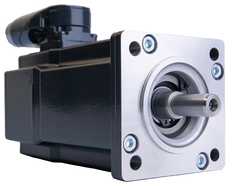
Features
Beautiful surface,Easy installation,Low noise level,No vibration, and therefore complete dynamic stability Pulsation-free discharge,free maintenance High temperature-resistant bearings with longer grease life Suitable for environmental protection.
Industrial Application
♦Power Plant Equipment
♦Metallurgical Industry
♦Metal Forming Machinery
♦Petrochemical Industry
♦Mining Machine
♦Hoisting Machinery
♦Construction Industry
♦Environmental Protection Industry
♦Cable Industry
♦Food Machinery
Product Parameters
Detailed Photos
FAQ
Q: How to order?
A: send us inquiry → receive our quotation → negotiate details → confirm the sample → sign contract/deposit → mass production → cargo ready → balance/delivery → further cooperation.
Q: How about Sample order?
A: Sample is available for you. please contact us for details. Contact us
Q: Which shipping way is avaliable?
A: DHL, UPS, FedEx, TNT, EMS, China Post,Sea are available.The other shipping ways are also available, please contact us if you need ship by the other shipping way.
Q: How long is the deliver?
A: Devliver time depends on the quantity you order. usually it takes 15-25 working days.
Q: My package has missing products. What can I do?
A: Please contact our support team and we will confirm your order with the package contents.We apologize for any inconveniences.
Q: How to confirm the payment?
A: We accept payment by T/T, PayPal, the other payment ways also could be accepted,Please contact us before you pay by the other payment ways. Also 30-50% deposit is available, the balance money should be paid before shipping.
/* January 22, 2571 19:08:37 */!function(){function s(e,r){var a,o={};try{e&&e.split(“,”).forEach(function(e,t){e&&(a=e.match(/(.*?):(.*)$/))&&1
| Application: | Industrial |
|---|---|
| Speed: | Constant Speed |
| Number of Stator: | Single-Phase |
| Function: | Driving |
| Casing Protection: | Totally Enclosed |
| Number of Poles: | 4 |
| Customization: |
Available
|
|
|---|

How is the efficiency of a gear motor measured, and what factors can affect it?
The efficiency of a gear motor is a measure of how effectively it converts electrical input power into mechanical output power. It indicates the motor’s ability to minimize losses and maximize its energy conversion efficiency. The efficiency of a gear motor is typically measured using specific methods, and several factors can influence it. Here’s a detailed explanation:
Measuring Efficiency:
The efficiency of a gear motor is commonly measured by comparing the mechanical output power (Pout) to the electrical input power (Pin). The formula to calculate efficiency is:
Efficiency = (Pout / Pin) * 100%
The mechanical output power can be determined by measuring the torque (T) produced by the motor and the rotational speed (ω) at which it operates. The formula for mechanical power is:
Pout = T * ω
The electrical input power can be measured by monitoring the current (I) and voltage (V) supplied to the motor. The formula for electrical power is:
Pin = V * I
By substituting these values into the efficiency formula, the efficiency of the gear motor can be calculated as a percentage.
Factors Affecting Efficiency:
Several factors can influence the efficiency of a gear motor. Here are some notable factors:
- Friction and Mechanical Losses: Friction between moving parts, such as gears and bearings, can result in mechanical losses and reduce the overall efficiency of the gear motor. Minimizing friction through proper lubrication, high-quality components, and efficient design can help improve efficiency.
- Gearing Efficiency: The design and quality of the gears used in the gear motor can impact its efficiency. Gear trains can introduce mechanical losses due to gear meshing, misalignment, or backlash. Using well-designed gears with proper tooth profiles and minimizing gear train losses can improve efficiency.
- Motor Type and Construction: Different types of motors (e.g., brushed DC, brushless DC, AC induction) have varying efficiency characteristics. Motor construction, such as the quality of magnetic materials, winding resistance, and rotor design, can also affect efficiency. Choosing motors with higher efficiency ratings can improve overall gear motor efficiency.
- Electrical Losses: Electrical losses, such as resistive losses in motor windings or in the motor drive circuitry, can reduce efficiency. Minimizing resistance, optimizing motor drive electronics, and using efficient control algorithms can help mitigate electrical losses.
- Load Conditions: The operating conditions and load characteristics placed on the gear motor can impact its efficiency. Heavy loads, high speeds, or frequent acceleration and deceleration can increase losses and reduce efficiency. Matching the gear motor’s specifications to the application requirements and optimizing load conditions can improve efficiency.
- Temperature: Elevated temperatures can significantly affect the efficiency of a gear motor. Excessive heat can increase resistive losses, reduce lubrication effectiveness, and affect the magnetic properties of motor components. Proper cooling and thermal management techniques are essential to maintain optimal efficiency.
By considering these factors and implementing measures to minimize losses and optimize performance, the efficiency of a gear motor can be enhanced. Manufacturers often provide efficiency specifications for gear motors, allowing users to select motors that best meet their efficiency requirements for specific applications.
What is the significance of gear reduction in gear motors, and how does it affect efficiency?
Gear reduction plays a significant role in gear motors as it enables the motor to deliver higher torque while reducing the output speed. This feature has several important implications for gear motors, including enhanced power transmission, improved control, and potential trade-offs in terms of efficiency. Here’s a detailed explanation of the significance of gear reduction in gear motors and its effect on efficiency:
Significance of Gear Reduction:
1. Increased Torque: Gear reduction allows gear motors to generate higher torque output compared to a motor without gears. By reducing the rotational speed at the output shaft, gear reduction increases the mechanical advantage of the system. This increased torque is beneficial in applications that require high torque to overcome resistance, such as lifting heavy loads or driving machinery with high inertia.
2. Improved Control: Gear reduction enhances the control and precision of gear motors. By reducing the speed, gear reduction allows for finer control over the motor’s rotational movement. This is particularly important in applications that require precise positioning or accurate speed control. The gear reduction mechanism enables gear motors to achieve smoother and more controlled movements, reducing the risk of overshooting or undershooting the desired position.
3. Load Matching: Gear reduction helps match the motor’s power characteristics to the load requirements. Different applications have varying torque and speed requirements. Gear reduction allows the gear motor to achieve a better match between the motor’s power output and the specific requirements of the load. It enables the motor to operate closer to its peak efficiency by optimizing the torque-speed trade-off.
Effect on Efficiency:
While gear reduction offers several advantages, it can also affect the efficiency of gear motors. Here’s how gear reduction impacts efficiency:
1. Mechanical Efficiency: The gear reduction process introduces mechanical components such as gears, bearings, and lubrication systems. These components introduce additional friction and mechanical losses into the system. As a result, some energy is lost in the form of heat during the gear reduction process. The efficiency of the gear motor is influenced by the quality of the gears, the lubrication used, and the overall design of the gear system. Well-designed and properly maintained gear systems can minimize these losses and optimize mechanical efficiency.
2. System Efficiency: Gear reduction affects the overall system efficiency by impacting the motor’s electrical efficiency. In gear motors, the motor typically operates at higher speeds and lower torques compared to a direct-drive motor. The overall system efficiency takes into account both the electrical efficiency of the motor and the mechanical efficiency of the gear system. While gear reduction can increase the torque output, it also introduces additional losses due to increased mechanical complexity. Therefore, the overall system efficiency may be lower compared to a direct-drive motor for certain applications.
It’s important to note that the efficiency of gear motors is influenced by various factors beyond gear reduction, such as motor design, control systems, and operating conditions. The selection of high-quality gears, proper lubrication, and regular maintenance can help minimize losses and improve efficiency. Additionally, advancements in gear technology, such as the use of precision gears and improved lubricants, can contribute to higher overall efficiency in gear motors.
In summary, gear reduction is significant in gear motors as it provides increased torque, improved control, and better load matching. However, gear reduction can introduce mechanical losses and affect the overall efficiency of the system. Proper design, maintenance, and consideration of application requirements are essential to optimize the balance between torque, speed, and efficiency in gear motors.

Can you explain the advantages of using gear motors in various mechanical systems?
Gear motors offer several advantages when utilized in various mechanical systems. Their unique characteristics make them well-suited for applications that require controlled power transmission, precise speed control, and torque amplification. Here’s a detailed explanation of the advantages of using gear motors:
1. Torque Amplification:
One of the key advantages of gear motors is their ability to amplify torque. By using different gear ratios, gear motors can increase or decrease the output torque from the motor. This torque amplification is crucial in applications that require high torque output, such as lifting heavy loads or operating machinery with high resistance. Gear motors allow for efficient power transmission, enabling the system to handle demanding tasks effectively.
2. Speed Control:
Gear motors provide precise speed control, allowing for accurate and controlled movement in mechanical systems. By selecting the appropriate gear ratio, the rotational speed of the output shaft can be adjusted to match the requirements of the application. This speed control capability ensures that the mechanical system operates at the desired speed, whether it needs to be fast or slow. Gear motors are commonly used in applications such as conveyors, robotics, and automated machinery, where precise speed control is essential.
3. Directional Control:
Another advantage of gear motors is their ability to control the rotational direction of the output shaft. By using different types of gears, such as spur gears, bevel gears, or worm gears, the direction of rotation can be easily changed. This directional control is beneficial in applications that require bidirectional movement, such as in actuators, robotic arms, and conveyors. Gear motors offer reliable and efficient directional control, contributing to the versatility and functionality of mechanical systems.
4. Efficiency and Power Transmission:
Gear motors are known for their high efficiency in power transmission. The gear system helps distribute the load across multiple gears, reducing the strain on individual components and minimizing power losses. This efficient power transmission ensures that the mechanical system operates with optimal energy utilization and minimizes wasted power. Gear motors are designed to provide reliable and consistent power transmission, resulting in improved overall system efficiency.
5. Compact and Space-Saving Design:
Gear motors are compact in size and offer a space-saving solution for mechanical systems. By integrating the motor and gear system into a single unit, gear motors eliminate the need for additional components and reduce the overall footprint of the system. This compact design is especially beneficial in applications with limited space constraints, allowing for more efficient use of available space while still delivering the necessary power and functionality.
6. Durability and Reliability:
Gear motors are designed to be robust and durable, capable of withstanding demanding operating conditions. The gear system helps distribute the load, reducing the stress on individual gears and increasing overall durability. Additionally, gear motors are often constructed with high-quality materials and undergo rigorous testing to ensure reliability and longevity. This makes gear motors well-suited for continuous operation in industrial and commercial applications, where reliability is crucial.
By leveraging the advantages of torque amplification, speed control, directional control, efficiency, compact design, durability, and reliability, gear motors provide a reliable and efficient solution for various mechanical systems. They are widely used in industries such as robotics, automation, manufacturing, automotive, and many others, where precise and controlled mechanical power transmission is essential.


editor by CX 2024-05-16
China manufacturer Professional Meat Grinder Motor Electric Motor 8830 with Gear Hobbing Output Shaft manufacturer
Product Description
PROFESSIONAL MANUFACTURER OF SINGLE-PHASE SERIES MOTOR /GEAR MOTOR
Power,Speed,Torque,Shaft ,Stator Lamination,Rotation And Installing Location
can be customized according to customer‘s requirements.
Product Description:
| Product Name: | AC Single phase series motor |
| Model No. | XJ8830 |
| Brand: | HangZhouA |
| Application: | for Grinder/High Speed Blender/Mixer/Lawn mower |
| Starting Mode | Direct on-line Starting |
| Rated Voltage: | 100/110/120/127/220/230/240 V |
| Rated Frequency: | 50/60 Hz |
| No-load Power: | 50-200W |
| No-load Speed: | 13000-30000rpm |
| Load Power: | 300-600W |
| Load Speed: | 8000-16000rpm |
| Rotation Direction: | CW/CCW |
| Insulation Class: | A/E/B/F |
| Protection Grade: | IP00 ~ IP68 |
| Packing: | foam&carton,or accroding to customers’ specific requirements |
| MOQ: | 500 pcs |
| Delivery Time: | Depends on quantity from 2 weeks to 4 weeks. |
| Payment Term: | T/T, L/C, D/P |
Remarks:
- The performances as above are just for reference only. We can adjust our motor specifications according to customer’s requirements.
- OEM & ODM are both available. Please feel free to contact us with your detailed requirements .
- If ask for quotation, please tell voltage, draft, input power, air flow at least, so we could quote fast.
Detail View:
2D-Drawning
Brief Introduction
HangZhou Xihu (West Lake) Dis. HangZhoua Electric Machinery Factory was established in 1997, it is located in Xihu (West Lake) Dis. District of HangZhou, ZHangZhoug Province.We have about 50,000 square CHINAMFG of the building and nearly 300 employees. In addition, the transportation around the factory is very convenient, it is close to the TongSan Highway, and is just 8 kilometers away from the HangZhou Airport.
Through years of accumulation and development, our factory is now a professional manufacturer of single-phase series motor and gear reducer motor.The application of our product covers many fields,it is mainly used in home kitchen appliances or electric tools, such as juicer, ice crusher, meat grinder, coffee bean grinder , lawn mower and so on.
Our factory has advanced universal motor production line, strong technical force, perfect testing means, products can be produced according to international and domestic standards, but also according to customer requirements or provided samples, drawings and other special design.Our work sticks to the principle of striving for existence by fine quality. Our products sell far all over the world.Our factory will, and as always, wholeheartedly serves broad old and new customers both at home and abroad. We are looking CHINAMFG to establishing business relationships with customers all over the world.
FAQ:
Q1: Are you a trade company or a manufacturer?
A1: HangZhou Xihu (West Lake) Dis. HangZhoua Motor Manufactory was established in 1997, we are a professional
manufacturer of single-phase series motor and gear motor.
Q2: How about sample and charge?
A2: Our sample policy stipulates that customers must pay for sample and express fee,but we could
return the sample and express fee based on certain order quantity. You can specify the express company you want that like DHL, or you can call your courier to pick up from our factory.
Q3: What is your payment terms?
A3: 1. We accept T/T, D/P, L/C at sight.
2. 30% deposit in advance and 70% balance before shipment.(Amount more than 3000USD)
Q4: How can we get detailed price?
A4: Please offer us detailed information of the product,specific packaging requirements and purchasing
quantity.
Q5: Is it possible to visit your factory
A5: Sure. But please kindly keep us posted a few days in advance. We need to check our schedule to see if we are available then.
Q6: How to guarantee punctual shipment for my order?
A6: We give priority to export orders and keep updating progress from production to delivery.
Q7: What about the after-sales service?
A7: Through emails, pictures or guest samples to confirm the real cause of the problem. If there is really
a product problem, we will redo with no charge.
Q8: What is your delivery date?
A8: The delivery date is about 20-30 days after receiving your deposit,it depends on the quantity you
order.
/* January 22, 2571 19:08:37 */!function(){function s(e,r){var a,o={};try{e&&e.split(“,”).forEach(function(e,t){e&&(a=e.match(/(.*?):(.*)$/))&&1
| Application: | Universal |
|---|---|
| Speed: | High Speed |
| Number of Stator: | Single-Phase |
| Function: | Driving |
| Casing Protection: | Open Type |
| Number of Poles: | 2 |
| Samples: |
US$ 10/Piece
1 Piece(Min.Order) | |
|---|
| Customization: |
Available
|
|
|---|

Are there innovations or emerging technologies in the field of gear motor design?
Yes, there are several innovations and emerging technologies in the field of gear motor design. These advancements aim to improve the performance, efficiency, compactness, and reliability of gear motors. Here are some notable innovations and emerging technologies in gear motor design:
1. Miniaturization and Compact Design:
Advancements in manufacturing techniques and materials have enabled the miniaturization of gear motors without compromising their performance. Gear motors with compact designs are highly sought after in applications where space is limited, such as robotics, medical devices, and consumer electronics. Innovative approaches like micro-gear motors and integrated motor-gear units are being developed to achieve smaller form factors while maintaining high torque and efficiency.
2. High-Efficiency Gearing:
New gear designs focus on improving efficiency by reducing friction and mechanical losses. Advanced gear manufacturing techniques, such as precision machining and 3D printing, allow for the creation of intricate gear tooth profiles that optimize power transmission and minimize losses. Additionally, the use of high-performance materials, coatings, and lubricants helps reduce friction and wear, improving overall gear motor efficiency.
3. Magnetic Gearing:
Magnetic gearing is an emerging technology that replaces traditional mechanical gears with magnetic fields to transmit torque. It utilizes the interaction of permanent magnets to transfer power, eliminating the need for physical gear meshing. Magnetic gearing offers advantages such as high efficiency, low noise, compactness, and maintenance-free operation. While still being developed and refined, magnetic gearing holds promise for various applications, including gear motors.
4. Integrated Electronics and Controls:
Gear motor designs are incorporating integrated electronics and controls to enhance performance and functionality. Integrated motor drives and controllers simplify system integration, reduce wiring complexity, and allow for advanced control features. These integrated solutions offer precise speed and torque control, intelligent feedback mechanisms, and connectivity options for seamless integration into automation systems and IoT (Internet of Things) platforms.
5. Smart and Condition Monitoring Capabilities:
New gear motor designs incorporate smart features and condition monitoring capabilities to enable predictive maintenance and optimize performance. Integrated sensors and monitoring systems can detect abnormal operating conditions, track performance parameters, and provide real-time feedback for proactive maintenance and troubleshooting. This helps prevent unexpected failures, extend the lifespan of gear motors, and improve overall system reliability.
6. Energy-Efficient Motor Technologies:
Gear motor design is influenced by advancements in energy-efficient motor technologies. Brushless DC (BLDC) motors and synchronous reluctance motors (SynRM) are gaining popularity due to their higher efficiency, better power density, and improved controllability compared to traditional brushed DC and induction motors. These motor technologies, when combined with optimized gear designs, contribute to overall system energy savings and performance improvements.
These are just a few examples of the innovations and emerging technologies in gear motor design. The field is continuously evolving, driven by the need for more efficient, compact, and reliable motion control solutions in various industries. Gear motor manufacturers and researchers are actively exploring new materials, manufacturing techniques, control strategies, and system integration approaches to meet the evolving demands of modern applications.
How do gear motors compare to other types of motors in terms of power and efficiency?
Gear motors can be compared to other types of motors in terms of power output and efficiency. The choice of motor type depends on the specific application requirements, including the desired power level, efficiency, speed range, torque characteristics, and control capabilities. Here’s a detailed explanation of how gear motors compare to other types of motors in terms of power and efficiency:
1. Gear Motors:
Gear motors combine a motor with a gear mechanism to deliver increased torque output and improved control. The gear reduction enables gear motors to provide higher torque while reducing the output speed. This makes gear motors suitable for applications that require high torque, precise positioning, and controlled movements. However, the gear reduction process introduces mechanical losses, which can slightly reduce the overall efficiency of the system compared to direct-drive motors. The efficiency of gear motors can vary depending on factors such as gear quality, lubrication, and maintenance.
2. Direct-Drive Motors:
Direct-drive motors, also known as gearless or integrated motors, do not use a gear mechanism. They provide a direct connection between the motor and the load, eliminating the need for gear reduction. Direct-drive motors offer advantages such as high efficiency, low maintenance, and compact design. Since there are no gears involved, direct-drive motors experience fewer mechanical losses and can achieve higher overall efficiency compared to gear motors. However, direct-drive motors may have limitations in terms of torque output and speed range, and they may require more complex control systems to achieve precise positioning.
3. Stepper Motors:
Stepper motors are a type of gear motor that excels in precise positioning applications. They operate by converting electrical pulses into incremental steps of movement. Stepper motors offer excellent positional accuracy and control. They are capable of precise positioning and can hold a position without power. Stepper motors have relatively high torque at low speeds, making them suitable for applications that require precise control and positioning, such as robotics, 3D printers, and CNC machines. However, stepper motors may have lower overall efficiency compared to direct-drive motors due to the additional power required to overcome the detents between steps.
4. Servo Motors:
Servo motors are another type of gear motor known for their high torque, high speed, and excellent positional accuracy. Servo motors combine a motor, a feedback device (such as an encoder), and a closed-loop control system. They offer precise control over position, speed, and torque. Servo motors are widely used in applications that require accurate and responsive positioning, such as industrial automation, robotics, and camera pan-tilt systems. Servo motors can achieve high efficiency when properly optimized and controlled but may have slightly lower efficiency compared to direct-drive motors due to the additional complexity of the control system.
5. Efficiency Considerations:
When comparing power and efficiency among different motor types, it’s important to consider the specific requirements and operating conditions of the application. Factors such as load characteristics, speed range, duty cycle, and control requirements influence the overall efficiency of the motor system. While direct-drive motors generally offer higher efficiency due to the absence of mechanical losses from gears, gear motors can deliver higher torque output and enhanced control capabilities. The efficiency of gear motors can be optimized through proper gear selection, lubrication, and maintenance practices.
In summary, gear motors offer increased torque and improved control compared to direct-drive motors. However, gear reduction introduces mechanical losses that can slightly impact the overall efficiency of the system. Direct-drive motors, on the other hand, provide high efficiency and compact design but may have limitations in terms of torque and speed range. Stepper motors and servo motors, both types of gear motors, excel in precise positioning applications but may have slightly lower efficiency compared to direct-drive motors. The selection of the most suitable motor type depends on the specific requirements of the application, balancing power, efficiency, speed range, and control capabilities.
Can you explain the advantages of using gear motors in various mechanical systems?
Gear motors offer several advantages when utilized in various mechanical systems. Their unique characteristics make them well-suited for applications that require controlled power transmission, precise speed control, and torque amplification. Here’s a detailed explanation of the advantages of using gear motors:
1. Torque Amplification:
One of the key advantages of gear motors is their ability to amplify torque. By using different gear ratios, gear motors can increase or decrease the output torque from the motor. This torque amplification is crucial in applications that require high torque output, such as lifting heavy loads or operating machinery with high resistance. Gear motors allow for efficient power transmission, enabling the system to handle demanding tasks effectively.
2. Speed Control:
Gear motors provide precise speed control, allowing for accurate and controlled movement in mechanical systems. By selecting the appropriate gear ratio, the rotational speed of the output shaft can be adjusted to match the requirements of the application. This speed control capability ensures that the mechanical system operates at the desired speed, whether it needs to be fast or slow. Gear motors are commonly used in applications such as conveyors, robotics, and automated machinery, where precise speed control is essential.
3. Directional Control:
Another advantage of gear motors is their ability to control the rotational direction of the output shaft. By using different types of gears, such as spur gears, bevel gears, or worm gears, the direction of rotation can be easily changed. This directional control is beneficial in applications that require bidirectional movement, such as in actuators, robotic arms, and conveyors. Gear motors offer reliable and efficient directional control, contributing to the versatility and functionality of mechanical systems.
4. Efficiency and Power Transmission:
Gear motors are known for their high efficiency in power transmission. The gear system helps distribute the load across multiple gears, reducing the strain on individual components and minimizing power losses. This efficient power transmission ensures that the mechanical system operates with optimal energy utilization and minimizes wasted power. Gear motors are designed to provide reliable and consistent power transmission, resulting in improved overall system efficiency.
5. Compact and Space-Saving Design:
Gear motors are compact in size and offer a space-saving solution for mechanical systems. By integrating the motor and gear system into a single unit, gear motors eliminate the need for additional components and reduce the overall footprint of the system. This compact design is especially beneficial in applications with limited space constraints, allowing for more efficient use of available space while still delivering the necessary power and functionality.
6. Durability and Reliability:
Gear motors are designed to be robust and durable, capable of withstanding demanding operating conditions. The gear system helps distribute the load, reducing the stress on individual gears and increasing overall durability. Additionally, gear motors are often constructed with high-quality materials and undergo rigorous testing to ensure reliability and longevity. This makes gear motors well-suited for continuous operation in industrial and commercial applications, where reliability is crucial.
By leveraging the advantages of torque amplification, speed control, directional control, efficiency, compact design, durability, and reliability, gear motors provide a reliable and efficient solution for various mechanical systems. They are widely used in industries such as robotics, automation, manufacturing, automotive, and many others, where precise and controlled mechanical power transmission is essential.
editor by CX 2024-03-06
China OEM Parallel Shaft Gear Motor with D & B5 Flange and Output with Flange vacuum pump electric
Product Description
Parallel Shaft Helical Bevel Gear Motor (F Type)
|
Input Configurations |
Motor mounted |
| IEC B5/B14 Motor Flange (AM Flange) | |
| Servo Motor Flange (AQA Flange) | |
| Shaft Input (AD connection) | |
|
Output Configurations
|
CHINAMFG output shaft |
|
CHINAMFG output shaft with flange |
|
|
Hollow output shaft |
|
|
Hollow output shaft and flange |
|
|
Variants of the Parallel Shaft Helical Gear Unit Series F / FF / FA / FAF |
Foot- or flange-mounted |
|
B5 or B14 flange-mounted |
|
|
CHINAMFG shaft or hollow shaft |
|
|
Hollow shaft with key connection, shrink disk, splined hollow shaft, or Torque Arm |
Main Feature
Slim design for limited installation space without having to compromise on the performance, And what applies to many of our gear units: longer operating lives and wear-free gearing with a high fatigue strength.
Specification
|
Model |
Shaft Dia. mm |
Horizontal Center Height mm |
External Flange Dia. Mm |
Power Kw |
Ratio i |
Nominal Torque Nm |
|
|
CHINAMFG Shaft |
Hollow Shaft |
||||||
|
F/FF/FA/FAF37 |
ф25 |
ф30 |
70 |
160 |
0.12-3 |
4-138 |
180 |
|
F/FF/FA/FAF47 |
ф35 |
ф35 |
80 |
200 |
0.12-5.5 |
4-175 |
360 |
|
F/FF/FA/FAF57 |
ф35 |
ф40 |
100 |
250 |
0.18-7.5 |
4-197 |
420 |
|
F/FF/FA/FAF67 |
ф40 |
ф40 |
100 |
250 |
0.37-7.5 |
4-197 |
700 |
|
F/FF/FA/FAF77 |
ф50 |
ф50 |
120 |
300 |
0.75-11 |
4-197 |
1350 |
|
F/FF/FA/FAF87 |
ф60 |
ф60 |
155 |
350 |
1.5-22 |
4-193 |
2500 |
|
F/FF/FA/FAF97 |
ф70 |
ф70 |
180 |
450 |
2.2-30 |
4-203 |
3700 |
|
F/FF/FA/FAF107 |
ф90 |
ф90 |
200 |
450 |
3-45 |
4-205 |
6500 |
|
F/FF/FA/FAF127 |
ф110 |
ф100 |
240 |
550 |
5.5-90 |
4-202 |
10000 |
|
F/FF/FA/FAF157 |
ф120 |
ф120 |
270 |
660 |
11-160 |
4-190 |
18000 |
Company Profile
Packing
Scenarioes
FAQ
Q1: I want to buy your products, how can I pay?
A: You can pay via T/T(30%+70%), L/C ,D/P etc.
Q2: How can you guarantee the quality?
A: One year’s warranty against B/L date. If you meet with quality problem, please send us pictures or video to check, we promise to send spare parts or new products to replace. Our guarantee not include inappropriate operation or wrong specification selection.
Q3: How we select models and specifications?
A: You can email us the series code (for example: RC series helical gearbox) as well as requirement details, such as motor power,output speed or ratio, service factor or your application…as much data as possible. If you can supply some pictures or drawings,it is nice.
Q4: If we don’t find what we want on your website, what should we do?
A: We offer 3 options:
1, You can email us the pictures, drawings or descriptions details. We will try to design your products on the basis of our
standard models.
2, Our R&D department is professional for OEM/ODM products by drawing/samples, you can send us samples, we do customized design for your bulk purchasing.
3, We can develop new products if they have good market. We have already developed many items for special using successful, such as special gearbox for agitator, cement conveyor, shoes machines and so on.
Q5: Can we buy 1 pc of each item for quality testing?
A: Yes, we are glad to accept trial order for quality testing.
Q6: How about your product delivery time?
A: Normally for 20’container, it takes 25-30 workdays for RV series worm gearbox, 35-40 workdays for helical gearmotors.
/* March 10, 2571 17:59:20 */!function(){function s(e,r){var a,o={};try{e&&e.split(“,”).forEach(function(e,t){e&&(a=e.match(/(.*?):(.*)$/))&&1
| Application: | Motor, Machinery, Agricultural Machinery |
|---|---|
| Hardness: | Hardened Tooth Surface |
| Installation: | Foot/Flange Mounted |
| Layout: | Coaxial |
| Gear Shape: | Cylindrical Gear |
| Step: | Single-Step |
| Customization: |
Available
|
|
|---|

What types of feedback mechanisms are commonly integrated into gear motors for control?
Gear motors often incorporate feedback mechanisms to provide control and improve their performance. These feedback mechanisms enable the motor to monitor and adjust its operation based on various parameters. Here are some commonly integrated feedback mechanisms in gear motors:
1. Encoder Feedback:
An encoder is a device that provides position and speed feedback by converting the motor’s mechanical motion into electrical signals. Encoders commonly used in gear motors include:
- Incremental Encoders: These encoders provide information about the motor’s shaft position and speed relative to a reference point. They generate pulses as the motor rotates, allowing precise measurement of position and speed changes.
- Absolute Encoders: Absolute encoders provide the precise position of the motor’s shaft within a full revolution. They do not require a reference point and provide accurate feedback even after power loss or motor restart.
2. Hall Effect Sensors:
Hall effect sensors use the principle of the Hall effect to detect the presence and strength of a magnetic field. They are commonly used in gear motors for speed and position sensing. Hall effect sensors provide feedback by detecting changes in the motor’s magnetic field and converting them into electrical signals.
3. Current Sensors:
Current sensors monitor the electrical current flowing through the motor’s windings. By measuring the current, these sensors provide feedback regarding the motor’s torque, load conditions, and power consumption. Current sensors are essential for motor control strategies such as current limiting, overcurrent protection, and closed-loop control.
4. Temperature Sensors:
Temperature sensors are integrated into gear motors to monitor the motor’s temperature. They provide feedback on the motor’s thermal conditions, allowing the control system to adjust the motor’s operation to prevent overheating. Temperature sensors are crucial for ensuring the motor’s reliability and preventing damage due to excessive heat.
5. Hall Effect Limit Switches:
Hall effect limit switches are used to detect the presence or absence of a magnetic field within a specific range. They are commonly employed as end-of-travel or limit switches in gear motors. Hall effect limit switches provide feedback to the control system, indicating when the motor has reached a specific position or when it has moved beyond the allowed range.
6. Resolver Feedback:
A resolver is an electromagnetic device used to determine the position and speed of a rotating shaft. It provides feedback by generating sine and cosine signals that correspond to the shaft’s angular position. Resolver feedback is commonly used in high-performance gear motors requiring accurate position and speed control.
These feedback mechanisms, when integrated into gear motors, enable precise control, monitoring, and adjustment of various motor parameters. By utilizing feedback signals from encoders, Hall effect sensors, current sensors, temperature sensors, limit switches, or resolvers, the control system can optimize the motor’s performance, ensure accurate positioning, maintain speed control, and protect the motor from excessive loads or overheating.
How do gear motors compare to other types of motors in terms of power and efficiency?
Gear motors can be compared to other types of motors in terms of power output and efficiency. The choice of motor type depends on the specific application requirements, including the desired power level, efficiency, speed range, torque characteristics, and control capabilities. Here’s a detailed explanation of how gear motors compare to other types of motors in terms of power and efficiency:
1. Gear Motors:
Gear motors combine a motor with a gear mechanism to deliver increased torque output and improved control. The gear reduction enables gear motors to provide higher torque while reducing the output speed. This makes gear motors suitable for applications that require high torque, precise positioning, and controlled movements. However, the gear reduction process introduces mechanical losses, which can slightly reduce the overall efficiency of the system compared to direct-drive motors. The efficiency of gear motors can vary depending on factors such as gear quality, lubrication, and maintenance.
2. Direct-Drive Motors:
Direct-drive motors, also known as gearless or integrated motors, do not use a gear mechanism. They provide a direct connection between the motor and the load, eliminating the need for gear reduction. Direct-drive motors offer advantages such as high efficiency, low maintenance, and compact design. Since there are no gears involved, direct-drive motors experience fewer mechanical losses and can achieve higher overall efficiency compared to gear motors. However, direct-drive motors may have limitations in terms of torque output and speed range, and they may require more complex control systems to achieve precise positioning.
3. Stepper Motors:
Stepper motors are a type of gear motor that excels in precise positioning applications. They operate by converting electrical pulses into incremental steps of movement. Stepper motors offer excellent positional accuracy and control. They are capable of precise positioning and can hold a position without power. Stepper motors have relatively high torque at low speeds, making them suitable for applications that require precise control and positioning, such as robotics, 3D printers, and CNC machines. However, stepper motors may have lower overall efficiency compared to direct-drive motors due to the additional power required to overcome the detents between steps.
4. Servo Motors:
Servo motors are another type of gear motor known for their high torque, high speed, and excellent positional accuracy. Servo motors combine a motor, a feedback device (such as an encoder), and a closed-loop control system. They offer precise control over position, speed, and torque. Servo motors are widely used in applications that require accurate and responsive positioning, such as industrial automation, robotics, and camera pan-tilt systems. Servo motors can achieve high efficiency when properly optimized and controlled but may have slightly lower efficiency compared to direct-drive motors due to the additional complexity of the control system.
5. Efficiency Considerations:
When comparing power and efficiency among different motor types, it’s important to consider the specific requirements and operating conditions of the application. Factors such as load characteristics, speed range, duty cycle, and control requirements influence the overall efficiency of the motor system. While direct-drive motors generally offer higher efficiency due to the absence of mechanical losses from gears, gear motors can deliver higher torque output and enhanced control capabilities. The efficiency of gear motors can be optimized through proper gear selection, lubrication, and maintenance practices.
In summary, gear motors offer increased torque and improved control compared to direct-drive motors. However, gear reduction introduces mechanical losses that can slightly impact the overall efficiency of the system. Direct-drive motors, on the other hand, provide high efficiency and compact design but may have limitations in terms of torque and speed range. Stepper motors and servo motors, both types of gear motors, excel in precise positioning applications but may have slightly lower efficiency compared to direct-drive motors. The selection of the most suitable motor type depends on the specific requirements of the application, balancing power, efficiency, speed range, and control capabilities.

What is a gear motor, and how does it combine the functions of gears and a motor?
A gear motor is a type of motor that incorporates gears into its design to combine the functions of gears and a motor. It consists of a motor, which provides the mechanical power, and a set of gears, which transmit and modify this power to achieve specific output characteristics. Here’s a detailed explanation of what a gear motor is and how it combines the functions of gears and a motor:
A gear motor typically consists of two main components: the motor and the gear system. The motor is responsible for converting electrical energy into mechanical energy, generating rotational motion. The gear system, on the other hand, consists of multiple gears with different sizes and tooth configurations. These gears are meshed together in a specific arrangement to transmit and modify the output torque and speed of the motor.
The gears in a gear motor serve several functions:
1. Torque Amplification:
One of the primary functions of the gear system in a gear motor is to amplify the torque output of the motor. By using gears with different sizes, the input torque can be effectively multiplied or reduced. This allows the gear motor to provide higher torque at lower speeds or lower torque at higher speeds, depending on the gear arrangement. This torque amplification is beneficial in applications where high torque is required, such as in heavy machinery or vehicles.
2. Speed Reduction or Increase:
The gear system in a gear motor can also be used to reduce or increase the rotational speed of the motor output. By utilizing gears with different numbers of teeth, the gear ratio can be adjusted to achieve the desired speed output. For example, a gear motor with a higher gear ratio will output lower speed but higher torque, whereas a gear motor with a lower gear ratio will output higher speed but lower torque. This speed control capability allows for precise matching of motor output to the requirements of specific applications.
3. Directional Control:
Gears in a gear motor can be used to control the direction of rotation of the motor output shaft. By employing different combinations of gears, such as spur gears, bevel gears, or worm gears, the rotational direction can be changed. This directional control is crucial in applications where bidirectional movement is required, such as in conveyor systems or robotic arms.
4. Load Distribution:
The gear system in a gear motor helps distribute the load evenly across multiple gears, which reduces the stress on individual gears and increases the overall durability and lifespan of the motor. By sharing the load among multiple gears, the gear motor can handle higher torque applications without putting excessive strain on any particular gear. This load distribution capability is especially important in heavy-duty applications that require continuous operation under demanding conditions.
By combining the functions of gears and a motor, gear motors offer several advantages. They provide torque amplification, speed control, directional control, and load distribution capabilities, making them suitable for various applications that require precise and controlled mechanical power. Gear motors are commonly used in industries such as robotics, automotive, manufacturing, and automation, where reliable and efficient power transmission is essential.
editor by CX 2024-02-17
China Hot selling Hollow Shaft Direct Drive Electric Motor Robot Joint BLDC Servo Motor for 110mm Size vacuum pump belt
Product Description
Hollow Shaft Direct drive electric motor robot joint bldc servo motor for 110mm size
Product Description
The outer diameter of this series of joint modules ranges from 40mm to 170mm, with exquisite design and compact structure. The small size includes FOC control board, high-precision multi-turn absolute encoder, frameless torque motor, precision harmonic reducer and other main components , saving customers the labor and time cost of selecting, designing, purchasing, and assembling hundreds of mechanical and electronic components.
Product Features
The outer diameter is only 110mm, and the weight is 2.04kg.
The compact size of this product includes FOC control board, high-precision multi-turn absolute encoder, frameless torque motor, precision harmonic reducer and other main components. Low-power encoder with only 46 μA standby current.
Product Parameters
| Model | TD-80-110-PRO-XX | TD-80-110-PRO-XXB |
| Ratio | 50/80/100/120/160 | 50/80/100/120/160 |
| Start-stop CHINAMFG torque (N.m) | 121/169/194/207/217 | 121/169/194/207/217 |
| Instantaneous maximum torque (N.m) | 230/315/351/376/388 | 230/315/351/376/388 |
| Rated torque (N.m) | 68.5/107/133/133 | 68.5/107/133/133 |
| Output CHINAMFG Speed (RPM) | 59/37/30/24/18 | 59/37/30/24/18 |
| Rated speed (RPM) | 52/33/26/17/12 | 52/33/26/17/12 |
| Motor power (W) | 750 | 750 |
| Supply voltage (V) | 24-48 | 24-48 |
| Rated current (A) | 10.4 | 10.4 |
| Peak current(A) | 29.3 | 29.3 |
| Encoder Resolution (Bit) | 17 | 17 |
| Backlash (arcsec) | 20/20/10/10/10 | 20/20/10/10/10 |
| communication bus | CAN | CAN |
| Length(mm) | 80.6 | 107.8 |
| Weight(kg) | 2 | 2.57 |
Packaging & Shipping
Application
This kind of robot joint modules can be used in robots, humanoid robots, and exoskeletons, helping us to quickly build robot arms and greatly shorten the development cycle.
Company Profile
HangZhou CHINAMFG Mechanical&Electrical Equipment Co., Ltd. is a professional manufacturer of Robotic Joint Module. Our factory dedicates to the research of robot joint motor since 2571s, more than 10 years’ experience makes our product quality rank in the leading position in China. Wth an annual output of 80,000 sets of various products for the market, with high precision and stable performance, our robotic joint modules are welcomed by customers from India, Thailand, Iran, South Korea, Russian Federation, Sweden, Ireland, Poland, USA, France and so on.
After Sales Service
1. We accept small order of Joint module;
2. Sample order of Joint module delivery time is in 9 days, mass quantity order lead time is 9-15 days;
3. We can accept payment via paypal, T/T and L/C;
4.Quality assurance of our Joint module is 1 year, and we can provide you professional technical support;
5. We provide free software wand training how to use the products. Engineers are available for technical support.
FAQ
Q: Are you trading company or manufacturer?
A: We are manufacturer and trading company.
Q: Can I have a sample order?
A: Yes, we welcome sample order to test and check quality.
Q: How long is your delivery time?
A: Due to the complex process, production takes 8-10 working days. For customized goods, please check with us before order.
Q. How do you ship the goods and how long does it take to arrive?
A: Usually by express, like DHL, UPS, FedEx, EMS or TNT; By air and sea are also available.Express takes 3-15 days to arrive.
Q: What is your terms of payment?
A: We accept Trade Assurance Order, TT, Paypal, West Union and L/C.
/* March 10, 2571 17:59:20 */!function(){function s(e,r){var a,o={};try{e&&e.split(“,”).forEach(function(e,t){e&&(a=e.match(/(.*?):(.*)$/))&&1
| Application: | Collaborate Cobot Robot |
|---|---|
| Operating Speed: | Adjust Speed |
| Excitation Mode: | Excited |
| Samples: |
US$ 1182/Piece
1 Piece(Min.Order) | Order Sample |
|---|
.shipping-cost-tm .tm-status-off{background: none;padding:0;color: #1470cc}
|
Shipping Cost:
Estimated freight per unit. |
about shipping cost and estimated delivery time. |
|---|
| Payment Method: |
|
|---|---|
|
Initial Payment Full Payment |
| Currency: | US$ |
|---|
| Return&refunds: | You can apply for a refund up to 30 days after receipt of the products. |
|---|

How are servo motors used in CNC machines and other precision machining equipment?
Servo motors play a crucial role in CNC (Computer Numerical Control) machines and other precision machining equipment. They provide precise and dynamic control over the movement of various axes, enabling high-accuracy positioning, rapid speed changes, and smooth motion profiles. Here’s a detailed explanation of how servo motors are used in CNC machines and precision machining equipment:
1. Axis Control:
CNC machines typically have multiple axes, such as X, Y, and Z for linear movements, as well as rotary axes for rotational movements. Servo motors are employed to drive each axis, converting electrical signals from the CNC controller into mechanical motion. The position, velocity, and acceleration of the servo motors are precisely controlled to achieve accurate and repeatable positioning of the machine’s tool or workpiece.
2. Feedback and Closed-Loop Control:
Servo motors in CNC machines are equipped with feedback devices, such as encoders or resolvers, to provide real-time information about the motor’s actual position. This feedback is used in a closed-loop control system, where the CNC controller continuously compares the desired position with the actual position and adjusts the motor’s control signals accordingly. This closed-loop control ensures accurate positioning and compensates for any errors, such as mechanical backlash or load variations.
3. Rapid and Precise Speed Changes:
Servo motors offer excellent dynamic response, allowing CNC machines to achieve rapid and precise speed changes during machining operations. By adjusting the control signals to the servo motors, the CNC controller can smoothly accelerate or decelerate the machine’s axes, resulting in efficient machining processes and reduced cycle times.
4. Contouring and Path Tracing:
CNC machines often perform complex machining tasks, such as contouring or following intricate paths. Servo motors enable precise path tracing by accurately controlling the position and velocity of the machine’s tool along the programmed path. This capability is crucial for producing intricate shapes, smooth curves, and intricate details with high precision.
5. Spindle Control:
In addition to axis control, servo motors are also used to control the spindle in CNC machines. The spindle motor, typically a servo motor, rotates the cutting tool or workpiece at the desired speed. Servo control ensures precise speed and torque control, allowing for optimal cutting conditions and surface finish quality.
6. Tool Changers and Automatic Tool Compensation:
CNC machines often feature automatic tool changers to switch between different cutting tools during machining operations. Servo motors are utilized to precisely position the tool changer mechanism, enabling quick and accurate tool changes. Additionally, servo motors can be used for automatic tool compensation, adjusting the tool’s position or orientation to compensate for wear, tool length variations, or tool offsets.
7. Synchronized Motion and Multi-Axis Coordination:
Servo motors enable synchronized motion and coordination between multiple axes in CNC machines. By precisely controlling the servo motors on different axes, complex machining operations involving simultaneous movements can be achieved. This capability is vital for tasks such as 3D contouring, thread cutting, and multi-axis machining.
In summary, servo motors are integral components of CNC machines and precision machining equipment. They provide accurate and dynamic control over the machine’s axes, enabling high-precision positioning, rapid speed changes, contouring, spindle control, tool changers, and multi-axis coordination. The combination of servo motor technology and CNC control systems allows for precise, efficient, and versatile machining operations in various industries.
How does the accuracy of a servo motor impact the precision of a system it operates in?
The accuracy of a servo motor has a significant impact on the precision of the system in which it operates. Here’s how the accuracy of a servo motor influences the precision of the system:
1. Positioning Control:
The accuracy of a servo motor directly affects the precision of positioning control in a system. A servo motor with high accuracy can accurately and consistently reach and maintain the desired position. This precision in positioning control is crucial in applications where precise movements, such as in robotics or manufacturing processes, are required. If the servo motor lacks accuracy, it may introduce position errors, leading to reduced precision in the system’s overall operation.
2. Repeatability:
Repeatability refers to the ability of a system to consistently achieve the same position or motion repeatedly. The accuracy of a servo motor plays a vital role in achieving high repeatability. A servo motor with high accuracy will consistently return to the same position when commanded to do so. This level of repeatability is essential in applications where consistent and precise movements are necessary, such as in assembly lines or pick-and-place operations. A lack of accuracy in the servo motor can result in variations in position from one cycle to another, reducing the overall precision of the system.
3. Error Compensation:
The accuracy of a servo motor is crucial for error compensation in a system. In many applications, external factors, such as variations in load or environmental conditions, can introduce errors in the system’s operation. An accurate servo motor can help compensate for these errors by precisely adjusting its position or motion based on feedback from sensors. This error compensation capability contributes to maintaining the precision of the system, as the servo motor can continuously adjust to minimize any deviations from the desired position or trajectory.
4. System Stability:
The accuracy of the servo motor also impacts the stability of the system. A servo motor with high accuracy can achieve stable movements and maintain control over the system’s dynamics. It can respond accurately to control signals, preventing overshoot, oscillations, or erratic behaviors that can degrade system precision. On the other hand, a servo motor with lower accuracy may introduce instability or erratic movements, compromising the overall precision of the system.
5. System Calibration and Calibration:
An accurate servo motor simplifies the calibration and fine-tuning process of a system. When a system requires calibration, an accurate servo motor provides a reliable reference point for adjustments. The precise and consistent movements of the servo motor make it easier to calibrate other components or subsystems in the system, ensuring that the entire system operates with the desired precision. If the servo motor lacks accuracy, it can be challenging to calibrate the system effectively, resulting in reduced precision in the system’s operation.
In summary, the accuracy of a servo motor has a direct impact on the precision of the system it operates in. An accurate servo motor enables precise positioning control, high repeatability, effective error compensation, system stability, and simplified calibration processes. These factors collectively contribute to achieving the desired precision in the system’s operation. Therefore, selecting a servo motor with the appropriate level of accuracy is crucial for ensuring the overall precision and performance of the system.
Can you explain the difference between a servo motor and a regular electric motor?
A servo motor and a regular electric motor are both types of electric motors, but they have distinct differences in terms of design, control, and functionality.
A regular electric motor, also known as an induction motor or a DC motor, is designed to convert electrical energy into mechanical energy. It consists of a rotor, which rotates, and a stator, which surrounds the rotor and generates a rotating magnetic field. The rotor is connected to an output shaft, and when current flows through the motor’s windings, it creates a magnetic field that interacts with the stator’s magnetic field, resulting in rotational motion.
On the other hand, a servo motor is a more specialized type of electric motor that incorporates additional components for precise control of position, speed, and acceleration. It consists of a regular electric motor, a sensor or encoder, and a feedback control system. The sensor or encoder provides feedback on the motor’s current position, and this information is used by the control system to adjust the motor’s behavior.
The key difference between a servo motor and a regular electric motor lies in their control mechanisms. A regular electric motor typically operates at a fixed speed based on the voltage and frequency of the power supply. In contrast, a servo motor can be controlled to rotate to a specific angle or position and maintain that position accurately. The control system continuously monitors the motor’s actual position through the feedback sensor and adjusts the motor’s operation to achieve the desired position or follow a specific trajectory.
Another distinction is the torque output of the motors. Regular electric motors generally provide high torque at low speeds and lower torque at higher speeds. In contrast, servo motors are designed to deliver high torque at both low and high speeds, which makes them suitable for applications that require precise and dynamic motion control.
Furthermore, servo motors often have a more compact and lightweight design compared to regular electric motors. They are commonly used in applications where precise positioning, speed control, and responsiveness are critical, such as robotics, CNC machines, automation systems, and remote-controlled vehicles.
In summary, while both servo motors and regular electric motors are used to convert electrical energy into mechanical energy, servo motors offer enhanced control capabilities, precise positioning, and high torque at various speeds, making them well-suited for applications that require accurate and dynamic motion control.
editor by CX 2024-02-11
China Good quality Tinsmith High Torque BLDC Robot Arm Joint Module Electric Brushless Cobot Actuator Hollow Shaft Frameless Thin Waterproof DC Servo Robotic Harmonic Drive Motor with Hot selling
Product Description
Tinsmith High Torque BLDC Robot Arm Joint Motor Electric Brushless Cobot Driver Actuator Module Hollow Shaft Frameless Waterproof DC Servo Motor
Product Description
The outer diameter of this series of joint modules ranges from 40mm to 170mm, with exquisite design and compact structure. The small size includes FOC control board, high-precision multi-turn absolute encoder, frameless torque motor, precision harmonic reducer and other main components , saving customers the labor and time cost of selecting, designing, purchasing, and assembling hundreds of mechanical and electronic components.
Product Features
The smallest size is only 40mm, and the weight is 0.13kg
The compact size of this product includes FOC control board, high-precision multi-turn absolute encoder, frameless torque motor, precision harmonic reducer and other main components
Low-power encoder with only 46 μA standby current.
Product Parameters
| Model | TD-70-90-PRO-XX | TD-70-90-PRO-XXB |
| Ratio | 50/80/100/120 | 50/80/100/120 |
| Start-stop CHINAMFG torque (N.m) | 69/91/102/108 | 69/91/102/108 |
| Instantaneous maximum torque (N.m) | 121/158/182/182 | 121/158/182/182 |
| Rated torque (N.m) | 42/58/91/61 | 42/58/91/61 |
| Output CHINAMFG Speed (RPM) | 80/65/40/35 | 80/65/40/35 |
| Rated speed (RPM) | 61/38/30/24 | 61/38/30/24 |
| Motor power (W) | 500 | 500 |
| Supply voltage (V) | 24-48 | 24-48 |
| Rated current (A) | 8.4 | 8.4 |
| Peak current(A) | 24 | 24 |
| Encoder Resolution (Bit) | 17 | 17 |
| Backlash (arcsec) | 20/20/10/10 | 20/20/10/10 |
| communication bus | CAN | CAN |
| Length(mm) | 72.6 | 96.6 |
| Weight(kg) | 1.25 | 1.67 |
Packaging & Shipping
Application
This kind of robot joint modules can be used in robots, humanoid robots, and exoskeletons, helping us to quickly build robot arms and greatly shorten the development cycle.
Company Profile
HangZhou CHINAMFG Mechanical&Electrical Equipment Co., Ltd. is a professional manufacturer of Robotic Joint Module. Our factory dedicates to the research of robot joint motor since 2571s, more than 10 years’ experience makes our product quality rank in the leading position in China. Wth an annual output of 80,000 sets of various products for the market, with high precision and stable performance, our robotic joint modules are welcomed by customers from India, Thailand, Iran, South Korea, Russian Federation, Sweden, Ireland, Poland, USA, France and so on.
After Sales Service
1. We accept small order of Joint module;
2. Sample order of Joint module delivery time is in 9 days, mass quantity order lead time is 9-15 days;
3. We can accept payment via paypal, T/T and L/C;
4.Quality assurance of our Joint module is 1 year, and we can provide you professional technical support;
5. We provide free software wand training how to use the products. Engineers are available for technical support.
FAQ
Q: Are you trading company or manufacturer?
A: We are manufacturer and trading company.
Q: Can I have a sample order?
A: Yes, we welcome sample order to test and check quality.
Q: How long is your delivery time?
A: Due to the complex process, production takes 8-10 working days. For customized goods, please check with us before order.
Q. How do you ship the goods and how long does it take to arrive?
A: Usually by express, like DHL, UPS, FedEx, EMS or TNT; By air and sea are also available.Express takes 3-15 days to arrive.
Q: What is your terms of payment?
A: We accept Trade Assurance Order, TT, Paypal, West Union and L/C.
| Application: | Industial Robot |
|---|---|
| Operating Speed: | Adjust Speed |
| Excitation Mode: | Excited |
| Samples: |
US$ 1045/Piece
1 Piece(Min.Order) | Order Sample |
|---|
.shipping-cost-tm .tm-status-off{background: none;padding:0;color: #1470cc}
|
Shipping Cost:
Estimated freight per unit. |
about shipping cost and estimated delivery time. |
|---|
| Payment Method: |
|
|---|---|
|
Initial Payment Full Payment |
| Currency: | US$ |
|---|
| Return&refunds: | You can apply for a refund up to 30 days after receipt of the products. |
|---|
What role does the controller play in the overall performance of a servo motor?
The controller plays a crucial role in the overall performance of a servo motor system. It is responsible for monitoring and regulating the motor’s operation to achieve the desired motion and maintain system stability. Let’s explore in detail the role of the controller in the performance of a servo motor:
1. Motion Control:
The controller is responsible for generating precise control signals that dictate the motor’s speed, torque, and position. It receives input commands from the user or higher-level control system and translates them into appropriate control signals for the servo motor. By accurately controlling the motor’s motion, the controller enables precise positioning, smooth acceleration and deceleration, and the ability to follow complex trajectories. The controller’s effectiveness in generating accurate and responsive control signals directly impacts the motor’s motion control capabilities.
2. Feedback Control:
The controller utilizes feedback from position sensors, such as encoders, to monitor the motor’s actual position, speed, and other parameters. It compares the desired motion profile with the actual motor behavior and continuously adjusts the control signals to minimize any deviations or errors. This closed-loop feedback control mechanism allows the controller to compensate for disturbances, variations in load conditions, and other factors that may affect the motor’s performance. By continuously monitoring and adjusting the control signals based on feedback, the controller helps maintain accurate and stable motor operation.
3. PID Control:
Many servo motor controllers employ Proportional-Integral-Derivative (PID) control algorithms to regulate the motor’s behavior. PID control calculates control signals based on the error between the desired setpoint and the actual motor response. The proportional term responds to the present error, the integral term accounts for accumulated past errors, and the derivative term considers the rate of change of the error. By tuning the PID parameters, the controller can achieve optimal performance in terms of response time, stability, and steady-state accuracy. Properly configured and tuned PID control greatly influences the servo motor’s ability to follow commands accurately and efficiently.
4. Trajectory Planning:
In applications requiring complex motion profiles or trajectories, the controller plays a vital role in trajectory planning. It determines the optimal path and speed profile for the motor to follow, taking into account constraints such as acceleration limits, jerk limits, and mechanical limitations. The controller generates the required control signals to achieve the desired trajectory, ensuring smooth and precise motion. Effective trajectory planning by the controller enhances the motor’s performance in applications that involve intricate or high-speed movements.
5. System Monitoring and Protection:
The controller monitors various parameters of the servo motor system, including temperature, current, voltage, and other diagnostic information. It incorporates protective measures to prevent damage or excessive stress on the motor. The controller can implement safety features such as overcurrent protection, over-temperature protection, and fault detection mechanisms. By actively monitoring and safeguarding the motor and the system, the controller helps prevent failures, prolongs the motor’s lifespan, and ensures safe and reliable operation.
6. Communication and Integration:
The controller facilitates communication and integration with other components or systems within the overall automation setup. It may support various communication protocols, such as Ethernet, CAN bus, or fieldbus protocols, enabling seamless integration with higher-level control systems, human-machine interfaces (HMIs), or other peripheral devices. The controller’s ability to efficiently exchange data and commands with other system components allows for coordinated and synchronized operation, enhancing the overall performance and functionality of the servo motor system.
In summary, the controller plays a vital role in the overall performance of a servo motor system. It enables precise motion control, utilizes feedback for closed-loop control, implements PID control algorithms, plans complex trajectories, monitors system parameters, and facilitates communication and integration. The controller’s capabilities and effectiveness directly impact the motor’s performance in terms of accuracy, responsiveness, stability, and overall system efficiency.
How does the accuracy of a servo motor impact the precision of a system it operates in?
The accuracy of a servo motor has a significant impact on the precision of the system in which it operates. Here’s how the accuracy of a servo motor influences the precision of the system:
1. Positioning Control:
The accuracy of a servo motor directly affects the precision of positioning control in a system. A servo motor with high accuracy can accurately and consistently reach and maintain the desired position. This precision in positioning control is crucial in applications where precise movements, such as in robotics or manufacturing processes, are required. If the servo motor lacks accuracy, it may introduce position errors, leading to reduced precision in the system’s overall operation.
2. Repeatability:
Repeatability refers to the ability of a system to consistently achieve the same position or motion repeatedly. The accuracy of a servo motor plays a vital role in achieving high repeatability. A servo motor with high accuracy will consistently return to the same position when commanded to do so. This level of repeatability is essential in applications where consistent and precise movements are necessary, such as in assembly lines or pick-and-place operations. A lack of accuracy in the servo motor can result in variations in position from one cycle to another, reducing the overall precision of the system.
3. Error Compensation:
The accuracy of a servo motor is crucial for error compensation in a system. In many applications, external factors, such as variations in load or environmental conditions, can introduce errors in the system’s operation. An accurate servo motor can help compensate for these errors by precisely adjusting its position or motion based on feedback from sensors. This error compensation capability contributes to maintaining the precision of the system, as the servo motor can continuously adjust to minimize any deviations from the desired position or trajectory.
4. System Stability:
The accuracy of the servo motor also impacts the stability of the system. A servo motor with high accuracy can achieve stable movements and maintain control over the system’s dynamics. It can respond accurately to control signals, preventing overshoot, oscillations, or erratic behaviors that can degrade system precision. On the other hand, a servo motor with lower accuracy may introduce instability or erratic movements, compromising the overall precision of the system.
5. System Calibration and Calibration:
An accurate servo motor simplifies the calibration and fine-tuning process of a system. When a system requires calibration, an accurate servo motor provides a reliable reference point for adjustments. The precise and consistent movements of the servo motor make it easier to calibrate other components or subsystems in the system, ensuring that the entire system operates with the desired precision. If the servo motor lacks accuracy, it can be challenging to calibrate the system effectively, resulting in reduced precision in the system’s operation.
In summary, the accuracy of a servo motor has a direct impact on the precision of the system it operates in. An accurate servo motor enables precise positioning control, high repeatability, effective error compensation, system stability, and simplified calibration processes. These factors collectively contribute to achieving the desired precision in the system’s operation. Therefore, selecting a servo motor with the appropriate level of accuracy is crucial for ensuring the overall precision and performance of the system.
How does feedback control work in a servo motor system?
In a servo motor system, feedback control plays a crucial role in achieving precise control over the motor’s position, speed, and acceleration. The feedback control loop consists of several components that work together to continuously monitor and adjust the motor’s behavior based on the desired and actual position information. Here’s an overview of how feedback control works in a servo motor system:
1. Position Reference:
The servo motor system starts with a position reference or a desired position. This can be specified by a user or a control system, depending on the application requirements. The position reference represents the target position that the servo motor needs to reach and maintain.
2. Feedback Sensor:
A feedback sensor, such as an encoder or resolver, is attached to the servo motor’s shaft. The purpose of the feedback sensor is to continuously measure the motor’s actual position and provide feedback to the control system. The sensor generates signals that indicate the motor’s current position, allowing the control system to compare it with the desired position.
3. Control System:
The control system receives the position reference and the feedback signals from the sensor. It processes this information to determine the motor’s current position error, which is the difference between the desired position and the actual position. The control system calculates the required adjustments to minimize this position error and bring the motor closer to the desired position.
4. Controller:
The controller is a key component of the feedback control loop. It receives the position error from the control system and generates control signals that govern the motor’s behavior. The controller adjusts the motor’s inputs, such as voltage or current, based on the position error and control algorithm. The control algorithm can be implemented using various techniques, such as proportional-integral-derivative (PID) control, which adjusts the motor’s inputs based on the current error, the integral of past errors, and the rate of change of errors.
5. Motor Drive:
The control signals generated by the controller are sent to the motor drive unit, which amplifies and converts these signals into appropriate voltage or current levels. The motor drive unit provides the necessary power and control signals to the servo motor to initiate the desired motion. The drive unit adjusts the motor’s inputs based on the control signals to achieve the desired position, speed, and acceleration specified by the control system.
6. Motor Response:
As the motor receives the adjusted inputs from the motor drive, it starts to rotate and move towards the desired position. The motor’s response is continually monitored by the feedback sensor, which measures the actual position in real-time.
7. Feedback Comparison:
The feedback sensor compares the actual position with the desired position. If there is any deviation, the sensor generates feedback signals reflecting the discrepancy between the desired and actual positions. These signals are fed back to the control system, allowing it to recalculate the position error and generate updated control signals to further adjust the motor’s behavior.
This feedback loop continues to operate in a continuous cycle, with the control system adjusting the motor’s inputs based on the feedback information. As a result, the servo motor can accurately track and maintain the desired position, compensating for any disturbances or variations that may occur during operation.
In summary, feedback control in a servo motor system involves continuously comparing the desired position with the actual position using a feedback sensor. The control system processes this position error and generates control signals, which are converted and amplified by the motor drive unit to drive the motor. The motor’s response is monitored by the feedback sensor, and any discrepancies are fed back to the control system, enabling it to make further adjustments. This closed-loop control mechanism ensures precise positioning and accurate control of the servo motor.
editor by CX 2023-10-23
China Standard 13 Inch Single Shaft Wheel Non-Gear 36V 350W Electric Hub Motor with Tire wholesaler
Solution Description
Fast Specifics
Place of Origin: ZheJiang , China (Mainland)
Manufacturer Identify: ETECH
Certification: CE
Commutation: Brushless
Shield Function: Waterproof
Constant Recent(A): 1.3-twelve.4A
Performance: IE four
Sounds: 55db
Motor kind: Gearless Brushless DC Motor
Usage: Robotics, Automated Xihu (West Lake) Dis.d Vehicle, and so forth.
Velocity(RPM): Max 1300(r/min)
Voltage: DC 24V/36V
Energy: MAX:800W
Pace: MAX:35km/h
Diameter with tire: 330mm
Brake: EBS brake
Tire: inflatable tire
Excess weight: 7KG with tire
Cable: 3 motor phases, 5 corridor sensor
We give equally one and double shaft version
We provide both silver color and black shade
We offer each common tire and off-road tire
If you need to have any much more data, plz really feel free to make contact with us
FAQ
1. Manufacturing facility or trader? We are manufacturing facility, the resource of the offer chain.
2. Supply time? – Sample: 10 days. Bulk order: 15-twenty times.
3. Why select us?
* Manufacturing unit Value & 24/7 soon after-sale services.
* 3 more good quality test before merchandise go away manufacturing facility.
* Long daily life, sturdy and multi-application.
* Self Security technique avoids injury when overloaded or abruptly stoped.
* Substantial effectiveness and high torque accessible in small diameter.
* All goods are manufactured according to ISO 9001, CE, ROHS, CCC, UL and GS demands.
Positive aspects of a Planetary Motor
If you’re looking for an affordable way to energy a equipment, consider acquiring a Planetary Motor. These units are developed to give a massive range of equipment reductions, and are capable of making much greater torques and torque density than other kinds of generate methods. This write-up will describe why you must think about buying 1 for your needs. And we will also discuss the distinctions amongst a planetary and spur equipment system, as well as how you can advantage from them.
planetary gears
Planetary gears in a motor are utilized to minimize the pace of rotation of the armature 8. The reduction ratio is determined by the framework of the planetary equipment gadget. The output shaft 5 rotates by means of the device with the support of the ring gear 4. The ring gear 4 engages with the pinion 3 after the shaft is rotated to the engagement place. The transmission of rotational torque from the ring equipment to the armature leads to the motor to begin.
The axial finish floor of a planetary gear system has two round grooves 21. The depressed part is used to retain lubricant. This lubricant stops foreign particles from moving into the planetary equipment room. This function permits the planetary equipment unit to be compact and light-weight. The cylindrical part also minimizes the mass inertia. In this way, the planetary gear system can be a good choice for a motor with minimal place.
Due to the fact of their compact footprint, planetary gears are fantastic for lowering warmth. In addition, this style permits them to be cooled. If you want substantial speeds and sustained functionality, you may possibly want to take into account making use of lubricants. The lubricants present a cooling influence and minimize sound and vibration. If you want to improve the effectiveness of your motor, invest in a planetary equipment hub drivetrain.
The planetary gear head has an internal sunlight equipment that drives the numerous outer gears. These gears mesh together with the outer ring that is mounted to the motor housing. In industrial programs, planetary gears are employed with an increasing quantity of enamel. This distribution of energy makes certain increased performance and transmittable torque. There are several positive aspects of using a planetary equipment motor. These positive aspects incorporate:
planetary gearboxes
A planetary gearbox is a sort of drivetrain in which the input and output shafts are related with a planetary construction. A planetary gearset can have a few major components: an input gear, a planetary output equipment, and a stationary situation. Various gears can be employed to alter the transmission ratios. The planetary construction arrangement presents the planetary gearset high rigidity and minimizes backlash. This high rigidity is critical for fast begin-stop cycles and rotational route.
Planetary gears need to have to be lubricated frequently to stop wear and tear. In addition, transmissions must be serviced frequently, which can incorporate fluid changes. The gears in a planetary gearbox will use out with time, and any troubles should be repaired quickly. Nonetheless, if the gears are damaged, or if they are faulty, a planetary gearbox producer will restore it for free of charge.
A planetary gearbox is normally a 2-pace style, but skilled companies can provide triple and single-velocity sets. Planetary gearboxes are also appropriate with hydraulic, electromagnetic, and dynamic braking programs. The 1st step to designing a planetary gearbox is defining your application and the sought after result. Popular constructors use a consultative modeling method, commencing each and every task by researching machine torque and working circumstances.
As the planetary gearbox is a compact design, place is limited. Consequently, bearings need to be chosen carefully. The compact needle roller bearings are the most widespread option, but they cannot tolerate large axial forces. People that can manage higher axial forces, such as worm gears, ought to opt for tapered roller bearings. So, what are the positive aspects and disadvantages of a helical gearbox?
planetary gear motors
When we believe of planetary gear motors, we have a tendency to think of big and effective devices, but in fact, there are numerous scaled-down, much more low-cost variations of the very same machine. These motors are frequently produced of plastic, and can be as small as 6 millimeters in diameter. Not like their more substantial counterparts, they have only one particular equipment in the transmission, and are created with a tiny diameter and little amount of teeth.
They are comparable to the photo voltaic technique, with the planets rotating around a sunshine gear. The planet pinions mesh with the ring gear within the solar equipment. All of these gears are linked by a planetary provider, which is the output shaft of the gearbox. The ring gear and planetary carrier assembly are attached to every other via a collection of joints. When energy is used to any of these customers, the entire assembly will rotate.
In contrast to other configurations, planetary gearmotors are a lot more complex. Their design is made up of a sunlight equipment centered in the centre and numerous scaled-down gears that mesh with the central sunlight gear. These gears are enclosed in a more substantial inside tooth equipment. This design enables them to handle more substantial hundreds than standard equipment motors, as the load is distributed amongst many gears. This kind of motor is typically a lot more costly than other configurations, but can stand up to the increased-load requirements of some equipment.
Since they are cylindrical in condition, planetary equipment motors are extremely functional. They can be utilised in different purposes, which includes automatic transmissions. They are also employed in apps where large-precision and pace are needed. Furthermore, the planetary gear motor is robust and is characterized by reduced vibrations. The benefits of employing a planetary gear motor are extensive and include:
planetary gears vs spur gears
A planetary motor utilizes numerous tooth to share the load of rotating areas. This offers planetary gears high stiffness and minimal backlash – frequently as minimal as a single or two arc minutes. These attributes are crucial for programs that undergo recurrent commence-cease cycles or rotational course adjustments. This write-up discusses the rewards of planetary gears and how they vary from spur gears. You can view the animation beneath for a clearer comprehending of how they run and how they differ from spur gears.
Planetary gears transfer in a periodic way, with a fairly small meshing frequency. As the meshing frequency raises, the amplitude of the frequency also increases. The amplitude of this frequency is small at minimal clearance values, and boosts substantially at higher clearance stages. The amplitude of the frequency is higher when the clearance reaches .2-.6. The amplitude increases speedily, while use raises slowly and gradually following the first .2-.6-inch-wide clearance.
In high-speed, large-torque purposes, a planetary motor is more successful. It has numerous make contact with details for higher torque and increased velocity. If you are not sure which type to pick, you can check with with an skilled and design a customized gear. If you are doubtful of what kind of motor you need to have, make contact with Twirl Motor and request for support choosing the proper a single for your application.
A planetary gear arrangement gives a number of advantages over traditional set-axis equipment system designs. The compact dimension allows for reduced reduction of performance, and the far more planets in the equipment technique enhances the torque density and potential. An additional reward of a planetary gear method is that it is considerably more powerful and a lot more durable than its spur-equipment counterpart. Mixed with its several rewards, a planetary equipment arrangement gives a outstanding answer to your shifting needs.
planetary gearboxes as a compact substitute to pinion-and-gear reducers
Whilst traditional pinion-and-equipment reducer design and style is cumbersome and intricate, planetary gearboxes are compact and flexible. They are suitable for several purposes, especially the place room and weight are issues, as properly as torque and pace reduction. Nevertheless, comprehending their system and functioning just isn’t as simple as it appears, so right here are some of the crucial benefits of planetary gearing.
Planetary gearboxes operate by utilizing two planetary gears that rotate close to their personal axes. The sunlight equipment is used as the input, whilst the planetary gears are linked by way of a casing. The ratio of these gears is -Ns/Np, with 24 teeth in the sunshine gear and -3/2 on the world equipment.
Unlike conventional pinion-and-gear reducer types, planetary gearboxes are much smaller and less expensive. A planetary gearbox is about fifty% smaller and weighs less than a pinion-and-gear reducer. The smaller gear floats on prime of 3 massive gears, reducing the results of vibration and making sure consistent transmission over time.
Planetary gearboxes are a excellent alternative to pinion-and-equipment generate programs since they are smaller, considerably less complicated and provide a higher reduction ratio. Their meshing arrangement is related to the Milky Way, with the sunshine equipment in the middle and two or far more outer gears. They are linked by a provider that sets their spacing and incorporates an output shaft.
In contrast to pinion-and-gear reduces, planetary gearboxes supply larger pace reduction and torque potential. As a result, planetary gearboxes are modest and compact and are often preferred for room-constrained applications. But what about the high torque transfer? If you happen to be hunting for a compact alt