Product Description
PAD series is a hollow shaft planetary gearbox. It can be fast connected to any motor output shaft.The rotating output flange replaces the traditional output shaft, giving it a unique power transfer solution .
The PAD planetary gear on the shaft is supported by both ends of the full needle roller bearing, which enhances the torsion stiffness.The output shaft of PAD planetary gearbox is supported by 2 taper roller bearings for greater carrying capacity
The PAD hollow shaft planetary gearbox is with highest torsional stiffness, tilting moment and compactness.Backlash of PAD planetary gearbox can be to 1 arcmin.With the excellent positioning performance and high torque,PAD planetary gearbox is specially suitable for the motion occasion of high positioning precision, dynamic cyclic operations and compact solutions for motion control, automation, CNC machines and robotic.PAD planetary reducers have been used by famous manufacturing companies, such as Samsung, CHINAMFG and LG,etc.
Input size of PAD planetary gearbox is customizable,it can replace of similar models from other factories.So it is suitable for all kinds of servo motor and stepper motor.PAD inline planetary gearbox have various of speed reduction from 4-100.
PAD series planetary gearbox is with round output flange and output hollow shaft.
Good Quality High Torque PAD Series Planetary Gearbox Speed Geared Reducer with Square Flange Output
PAD sereis flange output planetary reducer features compact structure and high precision. Compared with other general gearbox, the use of PAD enables the installation space to be saved. The compact structure performs high torsional rigidity, and the taper roller bearing support provides high axial and moment load capacity.
PAD planetary gearbox is suitable for motion transmission where high positioning precision is required, and other automatic fields like dynamic cyclic operations, CNC machines and robotic industry.
Product Parameters
Detailed Photos
Precision planetary gear reducer is another name for planetary gear reducer in the industry. Its main transmission structure is planetary gear, sun gear and inner gear ring.
Compared with other gear reducers, precision planetary gear reducers have the characteristics of high rigidity, high precision (single stage can achieve less than 1 point), high transmission efficiency (single stage can achieve 97% – 98%), high torque/volume ratio, lifelong maintenance-free, etc. Most of them are installed on stepper motor and servo motor to reduce speed, improve torque and match inertia.
Company Profile
Certifications
Packaging & Shipping
/* March 10, 2571 17:59:20 */!function(){function s(e,r){var a,o={};try{e&&e.split(“,”).forEach(function(e,t){e&&(a=e.match(/(.*?):(.*)$/))&&1
| Application: | Motor, Electric Cars, Motorcycle, Machinery |
|---|---|
| Hardness: | Hardened Tooth Surface |
| Installation: | Vertical Type |
| Layout: | Coaxial |
| Gear Shape: | Planetary |
| Step: | Single-Step |
| Samples: |
US$ 100/Piece
1 Piece(Min.Order) | |
|---|
What maintenance practices are recommended for ensuring the longevity of servo motors?
Maintaining servo motors properly is crucial to ensure their longevity and reliable performance. Here are some recommended maintenance practices:
1. Regular Cleaning:
Regularly clean the servo motor to remove dust, debris, and other contaminants that can affect its performance. Use a soft brush or compressed air to clean the motor’s exterior and ventilation ports. Avoid using excessive force or liquid cleaners that could damage the motor.
2. Lubrication:
Follow the manufacturer’s recommendations for lubrication intervals and use the appropriate lubricant for the motor. Lubricate the motor’s bearings, gears, and other moving parts as per the specified schedule. Proper lubrication reduces friction, minimizes wear, and helps maintain optimal performance.
3. Inspections:
Regularly inspect the servo motor for signs of wear, damage, or loose connections. Check for any unusual noises, vibrations, or overheating during operation, as these can indicate potential issues. If any abnormalities are detected, consult the manufacturer’s documentation or seek professional assistance for further evaluation and repair.
4. Electrical Connections:
Ensure that all electrical connections to the servo motor, such as power cables and signal wires, are secure and properly insulated. Loose or damaged connections can lead to electrical problems, voltage fluctuations, or signal interference, which can affect the motor’s performance and longevity.
5. Environmental Considerations:
Take into account the operating environment of the servo motor. Ensure that the motor is protected from excessive moisture, dust, extreme temperatures, and corrosive substances. If necessary, use appropriate enclosures or protective measures to safeguard the motor from adverse environmental conditions.
6. Software and Firmware Updates:
Stay updated with the latest software and firmware releases provided by the servo motor manufacturer. These updates often include bug fixes, performance enhancements, and new features that can improve the motor’s functionality and reliability. Follow the manufacturer’s instructions for safely updating the motor’s software or firmware.
7. Training and Documentation:
Ensure that personnel responsible for the maintenance of servo motors are properly trained and familiar with the manufacturer’s guidelines and documentation. This includes understanding recommended maintenance procedures, safety precautions, and troubleshooting techniques. Regular training and access to up-to-date documentation are essential for effective servo motor maintenance.
8. Professional Servicing:
If a servo motor requires complex repairs or servicing beyond regular maintenance, it is advisable to consult a qualified technician or contact the manufacturer’s service center. Attempting to repair or modify the motor without proper expertise can lead to further damage or safety hazards.
By following these maintenance practices, servo motors can operate optimally and have an extended lifespan. Regular cleaning, lubrication, inspections, secure electrical connections, environmental considerations, software updates, training, and professional servicing all contribute to ensuring the longevity and reliable performance of servo motors.
How does the accuracy of a servo motor impact the precision of a system it operates in?
The accuracy of a servo motor has a significant impact on the precision of the system in which it operates. Here’s how the accuracy of a servo motor influences the precision of the system:
1. Positioning Control:
The accuracy of a servo motor directly affects the precision of positioning control in a system. A servo motor with high accuracy can accurately and consistently reach and maintain the desired position. This precision in positioning control is crucial in applications where precise movements, such as in robotics or manufacturing processes, are required. If the servo motor lacks accuracy, it may introduce position errors, leading to reduced precision in the system’s overall operation.
2. Repeatability:
Repeatability refers to the ability of a system to consistently achieve the same position or motion repeatedly. The accuracy of a servo motor plays a vital role in achieving high repeatability. A servo motor with high accuracy will consistently return to the same position when commanded to do so. This level of repeatability is essential in applications where consistent and precise movements are necessary, such as in assembly lines or pick-and-place operations. A lack of accuracy in the servo motor can result in variations in position from one cycle to another, reducing the overall precision of the system.
3. Error Compensation:
The accuracy of a servo motor is crucial for error compensation in a system. In many applications, external factors, such as variations in load or environmental conditions, can introduce errors in the system’s operation. An accurate servo motor can help compensate for these errors by precisely adjusting its position or motion based on feedback from sensors. This error compensation capability contributes to maintaining the precision of the system, as the servo motor can continuously adjust to minimize any deviations from the desired position or trajectory.
4. System Stability:
The accuracy of the servo motor also impacts the stability of the system. A servo motor with high accuracy can achieve stable movements and maintain control over the system’s dynamics. It can respond accurately to control signals, preventing overshoot, oscillations, or erratic behaviors that can degrade system precision. On the other hand, a servo motor with lower accuracy may introduce instability or erratic movements, compromising the overall precision of the system.
5. System Calibration and Calibration:
An accurate servo motor simplifies the calibration and fine-tuning process of a system. When a system requires calibration, an accurate servo motor provides a reliable reference point for adjustments. The precise and consistent movements of the servo motor make it easier to calibrate other components or subsystems in the system, ensuring that the entire system operates with the desired precision. If the servo motor lacks accuracy, it can be challenging to calibrate the system effectively, resulting in reduced precision in the system’s operation.
In summary, the accuracy of a servo motor has a direct impact on the precision of the system it operates in. An accurate servo motor enables precise positioning control, high repeatability, effective error compensation, system stability, and simplified calibration processes. These factors collectively contribute to achieving the desired precision in the system’s operation. Therefore, selecting a servo motor with the appropriate level of accuracy is crucial for ensuring the overall precision and performance of the system.
Can servo motors be used in robotics, and if so, how are they implemented?
Yes, servo motors are commonly used in robotics due to their precise control capabilities and suitability for a wide range of robotic applications. When implementing servo motors in robotics, several factors need to be considered. Here’s an overview of how servo motors are used and implemented in robotics:
1. Joint Actuation:
Servo motors are often used to actuate the joints of robotic systems. Each joint in a robot typically requires a motor to control its movement. Servo motors provide the necessary torque and angular control to accurately position the joint. They can rotate between specific angles, allowing the robot to achieve the desired configuration and perform precise movements.
2. Position Control:
Servo motors excel at position control, which is essential for robotics applications. They can accurately maintain a specific position and respond quickly to control signals. By incorporating servo motors in robotic joints, precise positioning control can be achieved, enabling the robot to perform tasks with accuracy and repeatability.
3. Closed-Loop Control:
Implementing servo motors in robotics involves utilizing closed-loop control systems. Feedback sensors, such as encoders or resolvers, are attached to the servo motors to provide real-time feedback on the motor’s position. This feedback is used to continuously adjust the motor’s behavior and ensure accurate positioning. Closed-loop control allows the robot to compensate for any errors or disturbances and maintain precise control over its movements.
4. Control Architecture:
In robotics, servo motors are typically controlled using a combination of hardware and software. The control architecture encompasses the control algorithms, microcontrollers or embedded systems, and communication interfaces. The control system receives input signals, such as desired joint positions or trajectories, and generates control signals to drive the servo motors. The control algorithms, such as PID control, are used to calculate the appropriate adjustments based on the feedback information from the sensors.
5. Kinematics and Dynamics:
When implementing servo motors in robotics, the kinematics and dynamics of the robot must be considered. The kinematics deals with the study of the robot’s motion and position, while the dynamics focuses on the forces and torques involved in the robot’s movement. Servo motors need to be properly sized and selected based on the robot’s kinematic and dynamic requirements to ensure optimal performance and stability.
6. Integration and Programming:
Servo motors in robotics need to be integrated into the overall robot system. This involves mechanical mounting and coupling the motors to the robot’s joints, connecting the feedback sensors, and integrating the control system. Additionally, programming or configuring the control software is necessary to define the desired movements and control parameters for the servo motors. This programming can be done using robot-specific programming languages or software frameworks.
By utilizing servo motors in robotics and implementing them effectively, robots can achieve precise and controlled movements. Servo motors enable accurate positioning, fast response times, and closed-loop control, resulting in robots that can perform tasks with high accuracy, repeatability, and versatility. Whether it’s a humanoid robot, industrial manipulator, or collaborative robot (cobot), servo motors play a vital role in their actuation and control.


editor by CX 2024-02-19
China high quality Customize Precision High Torque DC 12V Gearbox Motor for Automatic Window Door, Speed Reduce Metal Gears vacuum pump ac system
Product Description
We are a factory specialized in metal parts hardware & metal gearbox through powder metallurgy process .
A planetary gearbox is a gearbox with the input shaft and output shaft aligned it offers high torque transmission with good stiffness and low noise , in a more compact foot print than other gearbox types . It can supply a lot of speed reduction and torque in a small package with the fixed axis .
A planetary gear set is made up of 3 types of gears , a sun gear , planet gears and a ring gear . The sun gear at high speed is located at the center of the gears , and transmits torque to the planet gears which are typically mounted on the moveable carrier .The planet gears around the central axis rotation ,mesh with the sun gear and an outer ring gear . As all the planet carriers turns , it delivers low-speed, high-torque output .
Description:
Product Name : Speed reducer
Gearbox Type: Planetary
Material: Metal
Gear Ratio : 5:1 , 10:1 , 20:1 , 25:1 , 30:1 , 40:1 , 50:1 , 60:1…100:1 . optional
Planetary Gearbox advantages:
- Provides high torque at slow speeds .
- The shafts are made up of hardened and tempered alloy steel .
- Sun gears ,planet gears and ring gears are made of powder metallurgy and sintering steel .
- Low noise levels.
- Good quality taper roller bearings for input and output shafts .
- High efficiency .
- Increased repeatability . Its Its greater speed radial and axial load offers reliability and robustness, minimizing the misalignment of the gear. In addition, uniform transmission and low vibrations at different loads provide a perfect repeatability.
- Perfect precision: Most rotating angular stability improves the accuracy and reliability of the movement.
- Lower noise level because there is more surface contact. Rolling is much softer and jumps are virtually nonexistent.
- Greater durability: Due to its torsional rigidity and better rolling. To improve this feature, your bearings help reduce the losses that would occur by rubbing the shaft on the box directly. Thus, greater efficiency of the gear and a much smoother operation is achieved.
- Increased torque transmission: With more teeth in contact, the mechanism is able to transmit and withstand more torque. In addition, it does it in a more uniform manner.
- Very good levels of efficiency: Planetary reducers offer greater efficiency and thanks to its design and internal layout losses are minimized during their work. In fact, today, this type of drive mechanisms are those that offer greater efficiency.
- Maximum versatility: Its mechanism is contained in a cylindrical gearbox, which can be installed in almost any space.
PM process for custom metal planetary gearbox , geared motors .
The P/M process is an economical, environmentally clean, high production method for making parts exactly to or close to final dimensions. With little or no machining operations required.
At present, parts with a complicated shape, tight-dimensional tolerances, controlled density and properties can be manufactured by powder metallurgy methods. A technological process of powder metallurgy ensures high flexibility in the selection of physiochemical properties and other requirements, including:
- Production of structural parts with complex shapes .
- Controlled porosity .
- High mechanical strength and resistance to vibrations .
- Controlled properties.
- High mechanical strength and resistance to vibrations.
- High manufacturing precision and good surface quality
- Large number of production series .
- Good tolerances .
Custom metal parts
Workshop
/* March 10, 2571 17:59:20 */!function(){function s(e,r){var a,o={};try{e&&e.split(“,”).forEach(function(e,t){e&&(a=e.match(/(.*?):(.*)$/))&&1
| Application: | Motor, Electric Cars, Motorcycle, Machinery, Marine, Toy, Agricultural Machinery, Car |
|---|---|
| Hardness: | Hardened Tooth Surface |
| Installation: | Vertical Type |
| Layout: | Coaxial |
| Gear Shape: | Cylindrical Gear |
| Step: | Three-Step |
| Samples: |
US$ 2/Piece
1 Piece(Min.Order) | |
|---|
| Customization: |
Available
|
|
|---|

How is the efficiency of a gear motor measured, and what factors can affect it?
The efficiency of a gear motor is a measure of how effectively it converts electrical input power into mechanical output power. It indicates the motor’s ability to minimize losses and maximize its energy conversion efficiency. The efficiency of a gear motor is typically measured using specific methods, and several factors can influence it. Here’s a detailed explanation:
Measuring Efficiency:
The efficiency of a gear motor is commonly measured by comparing the mechanical output power (Pout) to the electrical input power (Pin). The formula to calculate efficiency is:
Efficiency = (Pout / Pin) * 100%
The mechanical output power can be determined by measuring the torque (T) produced by the motor and the rotational speed (ω) at which it operates. The formula for mechanical power is:
Pout = T * ω
The electrical input power can be measured by monitoring the current (I) and voltage (V) supplied to the motor. The formula for electrical power is:
Pin = V * I
By substituting these values into the efficiency formula, the efficiency of the gear motor can be calculated as a percentage.
Factors Affecting Efficiency:
Several factors can influence the efficiency of a gear motor. Here are some notable factors:
- Friction and Mechanical Losses: Friction between moving parts, such as gears and bearings, can result in mechanical losses and reduce the overall efficiency of the gear motor. Minimizing friction through proper lubrication, high-quality components, and efficient design can help improve efficiency.
- Gearing Efficiency: The design and quality of the gears used in the gear motor can impact its efficiency. Gear trains can introduce mechanical losses due to gear meshing, misalignment, or backlash. Using well-designed gears with proper tooth profiles and minimizing gear train losses can improve efficiency.
- Motor Type and Construction: Different types of motors (e.g., brushed DC, brushless DC, AC induction) have varying efficiency characteristics. Motor construction, such as the quality of magnetic materials, winding resistance, and rotor design, can also affect efficiency. Choosing motors with higher efficiency ratings can improve overall gear motor efficiency.
- Electrical Losses: Electrical losses, such as resistive losses in motor windings or in the motor drive circuitry, can reduce efficiency. Minimizing resistance, optimizing motor drive electronics, and using efficient control algorithms can help mitigate electrical losses.
- Load Conditions: The operating conditions and load characteristics placed on the gear motor can impact its efficiency. Heavy loads, high speeds, or frequent acceleration and deceleration can increase losses and reduce efficiency. Matching the gear motor’s specifications to the application requirements and optimizing load conditions can improve efficiency.
- Temperature: Elevated temperatures can significantly affect the efficiency of a gear motor. Excessive heat can increase resistive losses, reduce lubrication effectiveness, and affect the magnetic properties of motor components. Proper cooling and thermal management techniques are essential to maintain optimal efficiency.
By considering these factors and implementing measures to minimize losses and optimize performance, the efficiency of a gear motor can be enhanced. Manufacturers often provide efficiency specifications for gear motors, allowing users to select motors that best meet their efficiency requirements for specific applications.

Are there environmental benefits to using gear motors in certain applications?
Yes, there are several environmental benefits associated with the use of gear motors in certain applications. Gear motors offer advantages that can contribute to increased energy efficiency, reduced resource consumption, and lower environmental impact. Here’s a detailed explanation of the environmental benefits of using gear motors:
1. Energy Efficiency:
Gear motors can improve energy efficiency in various ways:
- Torque Conversion: Gear reduction allows gear motors to deliver higher torque output while operating at lower speeds. This enables the motor to perform tasks that require high torque, such as lifting heavy loads or driving machinery with high inertia, more efficiently. By matching the motor’s power characteristics to the load requirements, gear motors can operate closer to their peak efficiency, minimizing energy waste.
- Controlled Speed: Gear reduction provides finer control over the motor’s rotational speed. This allows for more precise speed regulation, reducing the likelihood of energy overconsumption and optimizing energy usage.
2. Reduced Resource Consumption:
The use of gear motors can lead to reduced resource consumption and environmental impact:
- Smaller Motor Size: Gear reduction allows gear motors to deliver higher torque with smaller, more compact motors. This reduction in motor size translates to reduced material and resource requirements during manufacturing. It also enables the use of smaller and lighter equipment, which can contribute to energy savings during operation and transportation.
- Extended Motor Lifespan: The gear mechanism in gear motors helps reduce the load and stress on the motor itself. By distributing the load more evenly, gear motors can help extend the lifespan of the motor, reducing the need for frequent replacements and the associated resource consumption.
3. Noise Reduction:
Gear motors can contribute to a quieter and more environmentally friendly working environment:
- Noise Dampening: Gear reduction can help reduce the noise generated by the motor. The gear mechanism acts as a noise dampener, absorbing and dispersing vibrations and reducing overall noise emission. This is particularly beneficial in applications where noise reduction is important, such as residential areas, offices, or noise-sensitive environments.
4. Precision and Control:
Gear motors offer enhanced precision and control, which can lead to environmental benefits:
- Precise Positioning: Gear motors, especially stepper motors and servo motors, provide precise positioning capabilities. This accuracy allows for more efficient use of resources, minimizing waste and optimizing the performance of machinery or systems.
- Optimized Control: Gear motors enable precise control over speed, torque, and movement. This control allows for better optimization of processes, reducing energy consumption and minimizing unnecessary wear and tear on equipment.
In summary, using gear motors in certain applications can have significant environmental benefits. Gear motors offer improved energy efficiency, reduced resource consumption, noise reduction, and enhanced precision and control. These advantages contribute to lower energy consumption, reduced environmental impact, and a more sustainable approach to power transmission and control. When selecting motor systems for specific applications, considering the environmental benefits of gear motors can help promote energy efficiency and sustainability.

What are the different types of gears used in gear motors, and how do they impact performance?
Various types of gears are used in gear motors, each with its unique characteristics and impact on performance. The choice of gear type depends on the specific requirements of the application, including torque, speed, efficiency, noise level, and space constraints. Here’s a detailed explanation of the different types of gears used in gear motors and their impact on performance:
1. Spur Gears:
Spur gears are the most common type of gears used in gear motors. They have straight teeth that are parallel to the gear’s axis and mesh with another spur gear to transmit power. Spur gears provide high efficiency, reliable operation, and cost-effectiveness. However, they can generate significant noise due to the meshing of teeth, and they may produce axial thrust forces. Spur gears are suitable for applications that require high torque transmission and moderate to high rotational speeds.
2. Helical Gears:
Helical gears have angled teeth that are cut at an angle to the gear’s axis. This helical tooth configuration enables gradual engagement and smoother tooth contact, resulting in reduced noise and vibration compared to spur gears. Helical gears provide higher load-carrying capacity and are suitable for applications that require high torque transmission and moderate to high rotational speeds. They are commonly used in gear motors where low noise operation is desired, such as in automotive applications and industrial machinery.
3. Bevel Gears:
Bevel gears have teeth that are cut on a conical surface. They are used to transmit power between intersecting shafts, usually at right angles. Bevel gears can have straight teeth (straight bevel gears) or curved teeth (spiral bevel gears). These gears provide efficient power transmission and precise motion control in applications where shafts need to change direction. Bevel gears are commonly used in gear motors for applications such as steering systems, machine tools, and printing presses.
4. Worm Gears:
Worm gears consist of a worm (a type of screw) and a mating gear called a worm wheel or worm gear. The worm has a helical thread that meshes with the worm wheel, resulting in a compact and high gear reduction ratio. Worm gears provide high torque transmission, low noise operation, and self-locking properties, which prevent reverse motion. They are commonly used in gear motors for applications that require high gear reduction and locking capabilities, such as in lifting mechanisms, conveyor systems, and machine tools.
5. Planetary Gears:
Planetary gears, also known as epicyclic gears, consist of a central sun gear, multiple planet gears, and an outer ring gear. The planet gears mesh with both the sun gear and the ring gear, creating a compact and efficient gear system. Planetary gears offer high torque transmission, high gear reduction ratios, and excellent load distribution. They are commonly used in gear motors for applications that require high torque and compact size, such as in robotics, automotive transmissions, and industrial machinery.
6. Rack and Pinion:
Rack and pinion gears consist of a linear rack (a straight toothed bar) and a pinion gear (a spur gear with a small diameter). The pinion gear meshes with the rack to convert rotary motion into linear motion or vice versa. Rack and pinion gears provide precise linear motion control and are commonly used in gear motors for applications such as linear actuators, CNC machines, and steering systems.
The choice of gear type in a gear motor depends on factors such as the desired torque, speed, efficiency, noise level, and space constraints. Each type of gear offers specific advantages and impacts the performance of the gear motor differently. By selecting the appropriate gear type, gear motors can be optimized for their intended applications, ensuring efficient and reliable power transmission.
editor by CX 2024-02-11
China wholesaler High Precision High Torque Durable Servo Motor Planetary Robot Gear Box Flange Reducer Helical Gearbox Stepping Motor vacuum pump and compressor
Product Description
Planetary Gearbox AB Series Square Flange Helical Bevel Planetary Transmission Gearboxes Servo Motor
Product Overview:
Precision planetary gear reducer is another name for planetary gear reducer in the industry. Its main transmission structure is planetary gear, sun gear and inner gear ring.
Compared with other gear reducers, precision planetary gear reducers have the characteristics of high rigidity, high precision (single stage can achieve less than 1 point), high transmission efficiency (single stage can achieve 97% – 98%), high torque/volume ratio, lifelong maintenance-free, etc. Most of them are installed on stepper motor and servo motor to reduce speed, improve torque and match inertia.
AB series precision planetary gear box reducer AB60/90/115/142/180/220
features:
AB-series reducer features:
1. Helical gear design The reduction mechanism adopts the helical gear design, and its tooth shape meshing rate is more than twice that of the general spur gear, and has the characteristics of smooth operation, low noise, high output torque and low backlash
2. Collet type locking mechanism The connection between the input end and the motor adopts a collet-type locking mechanism and undergoes dynamic balance analysis to ensure the concentricity of the joint interface and zero-backlash power transmission at high input speeds
3. Modular design of motor connection board The unique modular design of the motor connecting plate and shaft is suitable for any brand and type of servo motor;
4. Efficient surface treatment technology The surface of the gearbox is treated with electroless nickel, and the connecting plate of the motor is treated with black anodic treatment to improve the environmental tolerance and corrosion resistance
5. One-piece gearbox body The gearbox and the inner ring gear adopt an integrated design, with compact structure, high precision and large output torque
6. Accurate concentricity of gear bar The sun gear made of the whole gear bar has strong rigidity and accurate concentricity
7. Solid, Single piece sun gear construction obtains precise concentricity with increased strength and rigidity. 8.Precision taper roller bearing support to increases radial and axial loading capacity.
Our Advantages
SERIES: AB/ ABR/ AD/ADS/ ADR/ AF/ AFR/ AFX/ AFXR/ AE/ AER/ AE/ AERS
PLF series, PLE series, ZPLF series, ZPLE series, AB series, ABR series and many other models are available.
Product Description
Planetary Gearbox AB Series Square Flange Helical Bevel Planetary Transmission Gearboxes Servo Motor
Advantages of the planetary gearbox:
Low backlash
High Efficiency
High Torque
High Input Speed
High Stability
High Reduction Ratio
Product Parameters
|
Name |
High Precision Planetary Gearbox |
|
Model |
AB042, AB060, AB060A, AB090A, AB115, AB142, AB180, AB220 |
|
Gearing Arrangement |
Planetary |
|
Effeiency withfull load |
≥97 |
|
Backlash |
≤5 |
|
Weight |
0.5~48kg |
|
Gear Type |
Helical Gear |
|
Gear stages |
1 stage, 2 stage |
|
Rated Torque |
14N.m-2000N.m |
|
Gear Ratio One-stage |
3, 4, 5, 6, 7, 8, 9, 10 |
|
Gear Ratio Two-stage |
15, 20, 25, 30, 35, 40, 45, 50, 60, 70, 80, 90, 100 |
|
Mounting Position |
Horizontal (foot mounted) or Vertical (flange mounted) |
|
Usage |
stepper motor, servo motor, AC motor, DC motor, etc |
Applications
Company Profile
Certifications
Packaging & Shipping
/* March 10, 2571 17:59:20 */!function(){function s(e,r){var a,o={};try{e&&e.split(“,”).forEach(function(e,t){e&&(a=e.match(/(.*?):(.*)$/))&&1
| Hardness: | Hardened Tooth Surface |
|---|---|
| Installation: | Vertical Type |
| Layout: | Coaxial |
| Gear Shape: | Planetary |
| Step: | Single-Step |
| Type: | Ab Series Gearbox, Gear Reducer |
| Samples: |
US$ 100/Piece
1 Piece(Min.Order) | |
|---|
Are there common issues or challenges associated with servo motor systems, and how can they be addressed?
Servo motor systems are widely used in various applications, but they can encounter common issues or challenges that affect their performance and reliability. Let’s explore some of these issues and discuss potential solutions:
1. Positioning and Tracking Errors:
One common challenge in servo motor systems is positioning and tracking errors. These errors can occur due to factors such as mechanical backlash, encoder resolution limitations, or disturbances in the system. To address this issue, careful calibration and tuning of the servo control system are necessary. This includes adjusting feedback gains, implementing feedback filtering techniques, and utilizing advanced control algorithms to improve the system’s accuracy and minimize errors. Additionally, employing high-resolution encoders and backlash compensation mechanisms can help enhance the positioning and tracking performance.
2. Vibration and Resonance:
Vibration and resonance can impact the performance of servo motor systems, leading to reduced accuracy and stability. These issues can arise from mechanical resonances within the system or external disturbances. To mitigate vibration and resonance problems, it is crucial to analyze the system’s dynamics and identify critical resonant frequencies. Implementing vibration dampening techniques such as mechanical isolation, using vibration-absorbing materials, or employing active vibration control methods can help minimize the effect of vibrations and improve the system’s performance.
3. Overheating and Thermal Management:
Servo motors can generate heat during operation, and inadequate thermal management can lead to overheating and potential performance degradation. To address this issue, proper cooling and thermal management techniques should be employed. This may involve using heat sinks, fans, or liquid cooling systems to dissipate heat efficiently. Ensuring adequate ventilation and airflow around the motor and avoiding excessive current or overloading can also help prevent overheating. Monitoring the motor’s temperature and implementing temperature protection mechanisms can further safeguard the motor from thermal damage.
4. Electrical Noise and Interference:
Electrical noise and interference can affect the performance and reliability of servo motor systems. These issues can arise from electromagnetic interference (EMI) or radio frequency interference (RFI) from nearby equipment or electrical sources. To mitigate electrical noise, proper shielding and grounding techniques should be employed. Using shielded cables, ferrite cores, and grounding the motor and control system can help minimize the impact of noise and interference. Additionally, employing filtering techniques and surge protection devices can further improve system robustness against electrical disturbances.
5. System Integration and Compatibility:
Integrating a servo motor system into a larger control system or automation setup can present challenges in terms of compatibility and communication. Ensuring proper compatibility between the servo motor and the control system is crucial. This involves selecting appropriate communication protocols, such as EtherCAT or Modbus, and ensuring compatibility with the control signals and interfaces. Employing standardized communication interfaces and protocols can facilitate seamless integration and interoperability. Additionally, thorough testing and verification of the system’s compatibility before deployment can help identify and address any integration issues.
6. Maintenance and Service:
Maintenance and service requirements are important considerations for servo motor systems. Regular maintenance, including lubrication, inspection, and cleaning, can help prevent issues related to wear and tear. Following manufacturer-recommended maintenance schedules and procedures is essential to ensure the longevity and optimal performance of the motor. In case of any malfunctions or failures, having access to technical support from the manufacturer or trained service personnel can help diagnose and address problems effectively.
By being aware of these common issues and challenges associated with servo motor systems and implementing appropriate solutions, it is possible to enhance the performance, reliability, and lifespan of the servo motor system. Regular monitoring, proactive maintenance, and continuous improvement can contribute to optimizing the overall operation and efficiency of the system.
How is the size of a servo motor determined based on application requirements?
The size of a servo motor is an important consideration when selecting a motor for a specific application. The size of the motor is determined based on various factors related to the application requirements. Let’s explore how the size of a servo motor is determined:
1. Torque Requirements:
One of the primary factors in determining the size of a servo motor is the torque requirements of the application. The motor should be able to generate sufficient torque to handle the load and overcome any resistance or friction in the system. The required torque depends on factors such as the weight of the load, the distance from the motor’s axis of rotation, and any additional forces acting on the system. By analyzing the torque requirements, one can select a servo motor with an appropriate size and torque rating to meet the application’s needs.
2. Speed and Acceleration Requirements:
The desired speed and acceleration capabilities of the application also influence the size of the servo motor. Different applications have varying speed and acceleration requirements, and the motor needs to be capable of achieving the desired performance. Higher speeds and accelerations may require larger motors with more powerful components to handle the increased forces and stresses. By considering the required speed and acceleration, one can determine the size of the motor that can meet these demands.
3. Inertia and Load Inertia Ratio:
The inertia of the load and the inertia ratio between the load and the servo motor are important considerations in sizing the motor. Inertia refers to the resistance of an object to changes in its rotational motion. If the load has a high inertia, it requires a servo motor with sufficient size and torque to accelerate and decelerate the load effectively. The inertia ratio, which is the ratio of the load inertia to the motor inertia, affects the motor’s ability to control the load’s motion accurately. A proper balance between the load and motor inertia is necessary to achieve optimal performance and stability in the system.
4. Duty Cycle and Continuous Operation:
The duty cycle and continuous operation requirements of the application also impact the motor size selection. Duty cycle refers to the ratio of the motor’s operating time to the total cycle time. Applications with high-duty cycles or continuous operation may require larger motors that can handle sustained operation without overheating or performance degradation. It is important to consider the motor’s continuous torque rating and thermal characteristics to ensure it can operate reliably under the given duty cycle requirements.
5. Physical Space Constraints:
The physical space available for installing the servo motor is another factor to consider. The motor’s dimensions should fit within the available space, considering factors such as motor length, diameter, and any mounting requirements. It is essential to ensure that the chosen motor can be easily integrated into the system without interfering with other components or causing space constraints.
6. Weight Limitations:
The weight limitations of the application may influence the motor size selection. If there are weight restrictions, such as in mobile or lightweight applications, it is necessary to choose a servo motor that is compact and lightweight while still providing the required performance. Lighter servo motors can help optimize the overall weight and balance of the system.
7. Cost Considerations:
Cost is also a factor to consider when determining the size of a servo motor. Larger motors with higher torque and performance capabilities tend to be more expensive. It is important to strike a balance between the required performance and the cost constraints of the application. Analyzing the cost-effectiveness and overall value of the motor in relation to the application requirements is essential.
By considering these factors, one can determine the appropriate size of a servo motor that can meet the specific application requirements. It is advisable to consult with manufacturers or experts in the field to ensure the chosen motor size aligns with the application needs and provides optimal performance and reliability.
Can servo motors be used in robotics, and if so, how are they implemented?
Yes, servo motors are commonly used in robotics due to their precise control capabilities and suitability for a wide range of robotic applications. When implementing servo motors in robotics, several factors need to be considered. Here’s an overview of how servo motors are used and implemented in robotics:
1. Joint Actuation:
Servo motors are often used to actuate the joints of robotic systems. Each joint in a robot typically requires a motor to control its movement. Servo motors provide the necessary torque and angular control to accurately position the joint. They can rotate between specific angles, allowing the robot to achieve the desired configuration and perform precise movements.
2. Position Control:
Servo motors excel at position control, which is essential for robotics applications. They can accurately maintain a specific position and respond quickly to control signals. By incorporating servo motors in robotic joints, precise positioning control can be achieved, enabling the robot to perform tasks with accuracy and repeatability.
3. Closed-Loop Control:
Implementing servo motors in robotics involves utilizing closed-loop control systems. Feedback sensors, such as encoders or resolvers, are attached to the servo motors to provide real-time feedback on the motor’s position. This feedback is used to continuously adjust the motor’s behavior and ensure accurate positioning. Closed-loop control allows the robot to compensate for any errors or disturbances and maintain precise control over its movements.
4. Control Architecture:
In robotics, servo motors are typically controlled using a combination of hardware and software. The control architecture encompasses the control algorithms, microcontrollers or embedded systems, and communication interfaces. The control system receives input signals, such as desired joint positions or trajectories, and generates control signals to drive the servo motors. The control algorithms, such as PID control, are used to calculate the appropriate adjustments based on the feedback information from the sensors.
5. Kinematics and Dynamics:
When implementing servo motors in robotics, the kinematics and dynamics of the robot must be considered. The kinematics deals with the study of the robot’s motion and position, while the dynamics focuses on the forces and torques involved in the robot’s movement. Servo motors need to be properly sized and selected based on the robot’s kinematic and dynamic requirements to ensure optimal performance and stability.
6. Integration and Programming:
Servo motors in robotics need to be integrated into the overall robot system. This involves mechanical mounting and coupling the motors to the robot’s joints, connecting the feedback sensors, and integrating the control system. Additionally, programming or configuring the control software is necessary to define the desired movements and control parameters for the servo motors. This programming can be done using robot-specific programming languages or software frameworks.
By utilizing servo motors in robotics and implementing them effectively, robots can achieve precise and controlled movements. Servo motors enable accurate positioning, fast response times, and closed-loop control, resulting in robots that can perform tasks with high accuracy, repeatability, and versatility. Whether it’s a humanoid robot, industrial manipulator, or collaborative robot (cobot), servo motors play a vital role in their actuation and control.
editor by CX 2024-01-10
China supplier 42mm NEMA17 Low Backlash High Precision Worm Gear Stepper Motor Step Motor with Worm Gearbox vacuum pump brakes
Product Description
Product Description
Worm Gear Stepper Motor
Made of pure copper, large torque, wear-resistant and rust-proof, mechanical self-locking ability, safe and convenient, single and double output shafts are optional, precise positioning type is strong, the backlash is as low as 15-18 arc minutes.
NEMA 17 (42*34mm)
gear ratio:1:17,1:31, 1:50, 1:100, 1:290,1:505;
NEMA 23 (57*55mm, 57*76mm)
gear ratio:1:5, 1:7.5, 1:10, 1:20, 1:25, 1:30, 1:40, 1:50, 1:60, 1:80;
Applications:
Medical equipment, testing instruments, robotics, 3D printing, ATM machine manufacturing, scientific research.
Product Parameters
42mm Nema17 Worm Gear Stepper Motor
| Worm Gear Material | Pure copper | |
| Max Allowable Radial Load | 200N | |
| Max Allowable Axial Load | 100N | |
| Backlash ( When No Load) | 1°~1.5° | |
| Output torque | 1~5N.m | |
| Motor Specification | Reduction Ratio | Output Torque (N.m) | Backhaul Gap | Motor Length(mm) | Reducer Length(mm) | Total Length(mm) | Efficient | Weight | |
| 42*34mm | 17 | 1.1 | 1°~1.5° | 34mm | 66mm | 100mm | 81% | 600g | |
| 31 | 2.2 | 81% | |||||||
| 50 | 3 | 73% | |||||||
| 100 | 5 | 73% | |||||||
| 290 | 5 | 65% | |||||||
| 505 | 5 | 50% | |||||||
Detailed Photos
Company Profile
ZheJiang UMot Technology Co., Ltd. specializes in R&D and sales of stepper motors, servo motors, linear modules and related motion control products, customizing and designing high-quality motor products for users with special needs around the world, and providing overall solutions for motion control systems. Products are exported to more than 30 countries and regions including the United States, Germany, France, Italy, Russia, and Switzerland. The company’s main products and system design have been widely used in automation control, precision instruments, medical equipment, smart home, 3D printing and many other fields.
Our company has been recognized as a high-tech enterprise by relevant departments, has a complete quality management system, has obtained ISO9001, CE, RoHs and other related certifications, and holds a number of electrical patent certificates. “Concentration, Professionalism, Concentration” in the field of automation of motor R&D and system control solutions is the company’s business purpose. “Be your most trusted partner” is the company’s service philosophy. We have always been aiming to “make first-class products with professional technology”, keep pace with the times, innovate constantly, and provide more users with better products and services.
FAQ
1. Shipping method:
1)International Express delivery DHL&FEDEX &UPS&TNT& 7-10days
2)Shipping by air 7-10 days
3)shipping by sea, delivery time depends on the destination port.
2. Technical Support:
We can provide you with professional technical support. And our products quality guarantee is 6 months. Also, we accept products customized.
3. Why should you buy from us, not from other suppliers?
Professional one-to-1 motor customized. The world’s large enterprise of choice for high-quality suppliers. ISO9001:2008 quality management system certification, through the CE, ROHS certification.
4. How to select models?
Before purchasing, please contact us to confirm model No. and specifications to avoid any misunderstanding.
5. Are you a factory?
Yes, we are a factory, and we produce stepper motor/driver, Servo motor/driver.
| Application: | Automation Control, Medical Equipment, Textile Mac |
|---|---|
| Speed: | Low Speed |
| Number of Stator: | Two-Phase |
| Excitation Mode: | HB-Hybrid |
| Function: | Control, Driving |
| Number of Poles: | 2 |
| Samples: |
US$ 42/Piece
1 Piece(Min.Order) | |
|---|
| Customization: |
Available
|
|
|---|
What are the maintenance requirements for gear motors, and how can longevity be maximized?
Gear motors, like any mechanical system, require regular maintenance to ensure optimal performance and longevity. Proper maintenance practices help prevent failures, minimize downtime, and extend the lifespan of gear motors. Here are some maintenance requirements for gear motors and ways to maximize their longevity:
1. Lubrication:
Regular lubrication is essential for gear motors to reduce friction, wear, and heat generation. The gears, bearings, and other moving parts should be properly lubricated according to the manufacturer’s recommendations. Lubricants should be selected based on the motor’s specifications and operating conditions. Regular inspection and replenishment of lubricants, as well as periodic oil or grease changes, should be performed to maintain optimal lubrication levels and ensure long-lasting performance.
2. Inspection and Cleaning:
Regular inspection and cleaning of gear motors are crucial for identifying any signs of wear, damage, or contamination. Inspecting the gears, bearings, shafts, and connections can help detect any abnormalities or misalignments. Cleaning the motor’s exterior and ventilation channels to remove dust, debris, or moisture buildup is also important in preventing malfunctions and maintaining proper cooling. Any loose or damaged components should be repaired or replaced promptly.
3. Temperature and Environmental Considerations:
Monitoring and controlling the temperature and environmental conditions surrounding gear motors can significantly impact their longevity. Excessive heat can degrade lubricants, damage insulation, and lead to premature component failure. Ensuring proper ventilation, heat dissipation, and avoiding overloading the motor can help manage temperature effectively. Similarly, protecting gear motors from moisture, dust, chemicals, and other environmental contaminants is vital to prevent corrosion and damage.
4. Load Monitoring and Optimization:
Monitoring and optimizing the load placed on gear motors can contribute to their longevity. Operating gear motors within their specified load and speed ranges helps prevent excessive stress, overheating, and premature wear. Avoiding sudden and frequent acceleration or deceleration, as well as preventing overloading or continuous operation near the motor’s maximum capacity, can extend its lifespan.
5. Alignment and Vibration Analysis:
Proper alignment of gear motor components, such as gears, couplings, and shafts, is crucial for smooth and efficient operation. Misalignment can lead to increased friction, noise, and premature wear. Regularly checking and adjusting alignment, as well as performing vibration analysis, can help identify any misalignment or excessive vibration that may indicate underlying issues. Addressing alignment and vibration problems promptly can prevent further damage and maximize the motor’s longevity.
6. Preventive Maintenance and Regular Inspections:
Implementing a preventive maintenance program is essential for gear motors. This includes establishing a schedule for routine inspections, lubrication, and cleaning, as well as conducting periodic performance tests and measurements. Following the manufacturer’s guidelines and recommendations for maintenance tasks, such as belt tension checks, bearing replacements, or gear inspections, can help identify and address potential issues before they escalate into major failures.
By adhering to these maintenance requirements and best practices, the longevity of gear motors can be maximized. Regular maintenance, proper lubrication, load optimization, temperature control, and timely repairs or replacements of worn components contribute to the reliable operation and extended lifespan of gear motors.

Can gear motors be used for precise positioning, and if so, what features enable this?
Yes, gear motors can be used for precise positioning in various applications. The combination of gear mechanisms and motor control features enables gear motors to achieve accurate and repeatable positioning. Here’s a detailed explanation of the features that enable gear motors to be used for precise positioning:
1. Gear Reduction:
One of the key features of gear motors is their ability to provide gear reduction. Gear reduction refers to the process of reducing the output speed of the motor while increasing the torque. By using the appropriate gear ratio, gear motors can achieve finer control over the rotational movement, allowing for more precise positioning. The gear reduction mechanism enables the motor to rotate at a slower speed while maintaining higher torque, resulting in improved accuracy and control.
2. High Resolution Encoders:
Many gear motors are equipped with high-resolution encoders. An encoder is a device that measures the position and speed of the motor shaft. High-resolution encoders provide precise feedback on the motor’s rotational position, allowing for accurate position control. The encoder signals are used in conjunction with motor control algorithms to ensure precise positioning by monitoring and adjusting the motor’s movement in real-time. The use of high-resolution encoders greatly enhances the gear motor’s ability to achieve precise and repeatable positioning.
3. Closed-Loop Control:
Gear motors with closed-loop control systems offer enhanced positioning capabilities. Closed-loop control involves continuously comparing the actual motor position (as measured by the encoder) with the desired position and making adjustments to minimize any position error. The closed-loop control system uses feedback from the encoder to adjust the motor’s speed, direction, and torque, ensuring accurate positioning even in the presence of external disturbances or variations in the load. Closed-loop control enables gear motors to actively correct for position errors and maintain precise positioning over time.
4. Stepper Motors:
Stepper motors are a type of gear motor that provides excellent precision and control for positioning applications. Stepper motors operate by converting electrical pulses into incremental steps of movement. Each step corresponds to a specific angular displacement, allowing precise positioning control. Stepper motors offer high step resolution, allowing for fine position adjustments. They are commonly used in applications that require precise positioning, such as robotics, 3D printers, and CNC machines.
5. Servo Motors:
Servo motors are another type of gear motor that excels in precise positioning tasks. Servo motors combine a motor, a feedback device (such as an encoder), and a closed-loop control system. They offer high torque, high speed, and excellent positional accuracy. Servo motors are capable of dynamically adjusting their speed and torque to maintain the desired position accurately. They are widely used in applications that require precise and responsive positioning, such as industrial automation, robotics, and camera pan-tilt systems.
6. Motion Control Algorithms:
Advanced motion control algorithms play a crucial role in enabling gear motors to achieve precise positioning. These algorithms, implemented in motor control systems or dedicated motion controllers, optimize the motor’s behavior to ensure accurate positioning. They take into account factors such as acceleration, deceleration, velocity profiling, and jerk control to achieve smooth and precise movements. Motion control algorithms enhance the gear motor’s ability to start, stop, and position accurately, reducing position errors and overshoot.
By leveraging gear reduction, high-resolution encoders, closed-loop control, stepper motors, servo motors, and motion control algorithms, gear motors can be effectively used for precise positioning in various applications. These features enable gear motors to achieve accurate and repeatable positioning, making them suitable for tasks that require precise control and reliable positioning performance.

Are there specific considerations for selecting the right gear motor for a particular application?
When selecting a gear motor for a specific application, several considerations need to be taken into account. The choice of the right gear motor is crucial to ensure optimal performance, efficiency, and reliability. Here’s a detailed explanation of the specific considerations for selecting the right gear motor for a particular application:
1. Torque Requirement:
The torque requirement of the application is a critical factor in gear motor selection. Determine the maximum torque that the gear motor needs to deliver to perform the required tasks. Consider both the starting torque (the torque required to initiate motion) and the operating torque (the torque required to sustain motion). Select a gear motor that can provide adequate torque to handle the load requirements of the application. It’s important to account for any potential torque spikes or variations during operation.
2. Speed Requirement:
Consider the desired speed range or specific speed requirements of the application. Determine the rotational speed (in RPM) that the gear motor needs to achieve to meet the application’s performance criteria. Select a gear motor with a suitable gear ratio that can achieve the desired speed at the output shaft. Ensure that the gear motor can maintain the required speed consistently and accurately throughout the operation.
3. Duty Cycle:
Evaluate the duty cycle of the application, which refers to the ratio of operating time to rest or idle time. Consider whether the application requires continuous operation or intermittent operation. Determine the duty cycle’s impact on the gear motor, including factors such as heat generation, cooling requirements, and potential wear and tear. Select a gear motor that is designed to handle the expected duty cycle and ensure long-term reliability and durability.
4. Environmental Factors:
Take into account the environmental conditions in which the gear motor will operate. Consider factors such as temperature extremes, humidity, dust, vibrations, and exposure to chemicals or corrosive substances. Choose a gear motor that is specifically designed to withstand and perform optimally under the anticipated environmental conditions. This may involve selecting gear motors with appropriate sealing, protective coatings, or materials that can resist corrosion and withstand harsh environments.
5. Efficiency and Power Requirements:
Consider the desired efficiency and power consumption of the gear motor. Evaluate the power supply available for the application and select a gear motor that operates within the specified voltage and current ranges. Assess the gear motor’s efficiency to ensure that it maximizes power transmission and minimizes wasted energy. Choosing an efficient gear motor can contribute to cost savings and reduced environmental impact.
6. Physical Constraints:
Assess the physical constraints of the application, including space limitations, mounting options, and integration requirements. Consider the size, dimensions, and weight of the gear motor to ensure it can be accommodated within the available space. Evaluate the mounting options and compatibility with the application’s mechanical structure. Additionally, consider any specific integration requirements, such as shaft dimensions, connectors, or interfaces that need to align with the application’s design.
7. Noise and Vibration:
Depending on the application, noise and vibration levels may be critical factors. Evaluate the acceptable noise and vibration levels for the application’s environment and operation. Choose a gear motor that is designed to minimize noise and vibration, such as those with helical gears or precision engineering. This is particularly important in applications that require quiet operation or where excessive noise and vibration may cause issues or discomfort.
By considering these specific factors when selecting a gear motor for a particular application, you can ensure that the chosen gear motor meets the performance requirements, operates efficiently, and provides reliable and consistent power transmission. It’s important to consult with gear motor manufacturers or experts to determine the most suitable gear motor based on the specific application’s needs.
editor by CX 2023-10-20
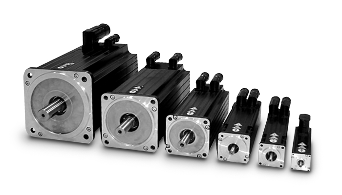
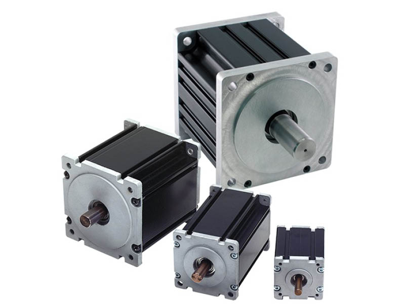
China OEM High Precision Pad60 90 Disc Planetary Reducer Servo Stepper Gearbox Reducer 86 57 Motor with Great quality
Product Description
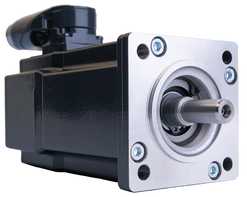
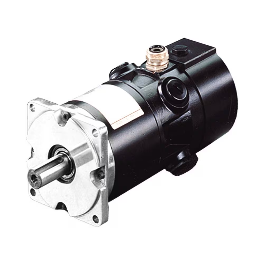
PAD series is a hollow shaft planetary gearbox. It can be fast connected to any motor output shaft.The rotating output flange replaces the traditional output shaft, giving it a unique power transfer solution .
The PAD planetary gear on the shaft is supported by both ends of the full needle roller bearing, which enhances the torsion stiffness.The output shaft of PAD planetary gearbox is supported by 2 taper roller bearings for greater carrying capacity
The PAD hollow shaft planetary gearbox is with highest torsional stiffness, tilting moment and compactness.Backlash of PAD planetary gearbox can be to 1 arcmin.With the excellent positioning performance and high torque,PAD planetary gearbox is specially suitable for the motion occasion of high positioning precision, dynamic cyclic operations and compact solutions for motion control, automation, CNC machines and robotic.PAD planetary reducers have been used by famous manufacturing companies, such as Samsung, CZPT and LG,etc.
Input size of PAD planetary gearbox is customizable,it can replace of similar models from other factories.So it is suitable for all kinds of servo motor and stepper motor.PAD inline planetary gearbox have various of speed reduction from 4-100.
PAD series planetary gearbox is with round output flange and output hollow shaft.
Good Quality High Torque PAD Series Planetary Gearbox Speed Geared Reducer with Square Flange Output
PAD sereis flange output planetary reducer features compact structure and high precision. Compared with other general gearbox, the use of PAD enables the installation space to be saved. The compact structure performs high torsional rigidity, and the taper roller bearing support provides high axial and moment load capacity.
PAD planetary gearbox is suitable for motion transmission where high positioning precision is required, and other automatic fields like dynamic cyclic operations, CNC machines and robotic industry.
Product Parameters
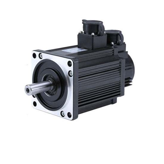
Detailed Photos
Precision planetary gear reducer is another name for planetary gear reducer in the industry. Its main transmission structure is planetary gear, sun gear and inner gear ring.
Compared with other gear reducers, precision planetary gear reducers have the characteristics of high rigidity, high precision (single stage can achieve less than 1 point), high transmission efficiency (single stage can achieve 97% – 98%), high torque/volume ratio, lifelong maintenance-free, etc. Most of them are installed on stepper motor and servo motor to reduce speed, improve torque and match inertia.
Company Profile
Certifications
Packaging & Shipping
| Application: | Motor, Electric Cars, Motorcycle, Machinery |
|---|---|
| Hardness: | Hardened Tooth Surface |
| Installation: | Vertical Type |
| Layout: | Coaxial |
| Gear Shape: | Planetary |
| Step: | Single-Step |
| Samples: |
US$ 100/Piece
1 Piece(Min.Order) | |
|---|

The Basics of a Gear Motor
The basic mechanism behind the gear motor is the principle of conservation of angular momentum. The smaller the gear, the more RPM it covers and the larger the gear, the more torque it produces. The ratio of angular velocity of two gears is called the gear ratio. Moreover, the same principle applies to multiple gears. This means that the direction of rotation of each adjacent gear is always the opposite of the one it is attached to.
Induction worm gear motor
If you’re looking for an electric motor that can deliver high torque, an Induction worm gear motor might be the right choice. This type of motor utilizes a worm gear attached to the motor to rotate a main gear. Because this type of motor is more efficient than other types of motors, it can be used in applications requiring massive reduction ratios, as it is able to provide more torque at a lower speed.
The worm gear motor is designed with a spiral shaft that is set into splines in another gear. The speed at which the worm gear rotates is dependent on the torque produced by the main gear. Induction worm gear motors are best suited for use in low-voltage applications such as electric cars, renewable energy systems, and industrial equipment. They come with a wide range of power-supply options, including twelve-volt, 24-volt, and 36-volt AC power supplies.
These types of motors can be used in many industrial settings, including elevators, airport equipment, food packaging facilities, and more. They also produce less noise than other types of motors, which makes them a popular choice for manufacturers with limited space. The efficiency of worm gearmotors makes them an excellent choice for applications where noise is an issue. Induction worm gear motors can be compact and extremely high-torque.
While the Induction worm gear motor is most widely used in industrial applications, there are other kinds of gearmotors available. Some types are more efficient than others, and some are more expensive than others. For your application, choosing the correct motor and gearbox combination is crucial to achieving the desired result. You’ll find that the Induction worm gear motor is an excellent choice for many applications. The benefits of an Induction worm gear motor can’t be overstated.
The DC gear motor is an excellent choice for high-end industrial applications. This type of gearmotor is smaller and lighter than a standard AC motor and can deliver up to 200 watts of torque. A gear ratio of three to two can be found in these motors, which makes them ideal for a wide range of applications. A high-quality DC gear motor is a great choice for many industrial applications, as they can be highly efficient and provide a high level of reliability.
Electric gear motors are a versatile and widely used type of electric motor. Nevertheless, there are some applications that don’t benefit from them, such as applications with high shaft speed and low torque. Applications such as fan motors, pump and scanning machines are examples of such high-speed and high-torque demands. The most important consideration when choosing a gearmotor is its efficiency. Choosing the right size will ensure the motor runs efficiently at peak efficiency and will last for years.
Parallel shaft helical gear motor
The FC series parallel shaft helical gearmotor is a compact, lightweight, and high-performance unit that utilizes a parallel shaft structure. Its compact design is complemented by high transmission efficiency and high carrying capacity. The motor’s material is 20CrMnTi alloy steel. The unit comes with either a flanged input or bolt-on feet for installation. Its low noise and compact design make it an ideal choice for a variety of applications.
The helical gears are usually arranged in two rows of one another. Each row contains one or more rows of teeth. The parallel row has the teeth in a helical pattern, while the helical rows are lined up parallelly. In addition to this, the cross helical gears have a point contact design and do not overlap. They can be either parallel or crossed. The helical gear motors can have any number of helical pairs, each with a different pitch circle diameter.
The benefits of the Parallel Shaft Helical Gearbox include high temperature and pressure handling. It is produced by skilled professionals using cutting-edge technology, and is widely recognized for its high performance. It is available in a range of technical specifications and is custom-made to suit individual requirements. These gearboxes are durable and low-noise and feature high reliability. You can expect to save up to 40% of your energy by using them.
The parallel shaft helical gear motors are designed to reduce the speed of a rotating part. The nodular cast iron housing helps make the unit robust in difficult environments, while the precision-machined gears provide quiet, vibration-free operation. These motors are available in double reduction, triple reduction, and quadruple reduction. The capacity ranges from 0.12 kW to 45 kW. You can choose from a wide variety of capacities, depending on the size of your gearing needs.
The SEW-EURODRIVE parallel shaft helical gearmotor is a convenient solution for space-constrained applications. The machine’s modular design allows for easy mounting and a wide range of ambient temperatures. They are ideal for a variety of mechanical applications, including conveyors, augers, and more. If you want a small footprint, the SEW-EURODRIVE parallel shaft helical gear motor is the best solution for you.
The parallel shaft helical gears are advantageous for both high and low speed applications. Parallel helical gears are also suitable for low speed and low duty applications. A good example of a cross-helix gear is the oil pump of an internal combustion engine. Both types of helical gears are highly reliable and offer vibration-free operation. They are more costly than conventional gear motors, but offer more durability and efficiency.
Helical gear unit
This helical gear unit is designed to operate under a variety of demanding conditions and can be used in a wide range of applications. Designed for long life and high torque density, this gear unit is available in a variety of torques and gear ratios. Its design and construction make it compatible with a wide range of critical mechanical systems. Common applications include conveyors, material handling, steel mills, and paper mills.
Designed for high-performance applications, the Heidrive helical gear unit provides superior performance and value. Its innovative design allows it to function well under a wide range of operating conditions and is highly resistant to damage. These gear motors can be easily combined with a helical gear unit. Their combined power output is 100 Nm, and they have a high efficiency of up to 90%. For more information about the helical gear motor, contact a Heidrive representative.
A helical gear unit can be classified by its reference section in the standard plane or the turning plane. Its center gap is the same as that of a spur gear, and its number of teeth is the same. In addition to this, the helical gear has a low axial thrust, which is another important characteristic. The helical gear unit is more efficient at transferring torque than a spur gear, and it is quieter, too.
These units are designed to handle large loads. Whether you are using them for conveyors, augers, or for any other application that involves high-speed motion, a helical gear unit will deliver maximum performance. A helical gear unit from Flender can handle 400,000 tasks with a high degree of reliability. Its high efficiency and high resistance to load ensures high plant availability. These gear motors are available in a variety of sizes, from single-speed to multi-speed.
PEC geared motors benefit from decades of design experience and high quality materials. They are robust, quiet, and offer excellent performance. They are available in multiple configurations and are dimensionally interchangeable with other major brands. The gear motors are manufactured as modular kits to minimize inventory. They can be fitted with additional components, such as backstops and fans. This makes it easy to customize your gear motors and save money while reducing costs.
Another type of helical gears is the double helical gear. The double helical gear unit has two helical faces with a gap between them. They are better for enclosed gear systems as they provide greater tooth overlap and smoother performance. Compared to double helical gears, they are smaller and more flexible than the Herringbone type. So, if you’re looking for a gear motor, a helical gear unit may be perfect for you.
editor by CX 2023-06-12
China factory NEMA 17 24V 42mm Electric Brushless DC Precision Planetary Gear Motor Gearbox Reducer BLDC Motor motor armature
Product Description
General Specification:
Step Angle Accuracy: ±5%
Resistance Accuracy: ±10%
Inductance Accuracy: ±20%
Temperature Rise: 80°C Max
Ambient Temperature: -15°C~+50°C
Insulation Resistance: 100MΩ Min., 500VDC
Dielectric Strength: 500VAC for 1 minute
Shaft Radial Play: 0.02Max (450g-load)
Shaft Axial Play: 0.08Max (450g-load)
Specification:
| Model | |||||
| Specification | Unit | JK42BLS01 | JK42BLS02 | JK42BLS03 | JK42BLS04 |
| Number Of Phase | Phase | 3 | |||
| Number Of Poles | Poles | 8 | |||
| Rated Voltage | VDC | 24 | |||
| Rated Speed | Rpm | 4000 | |||
| Rated Torque | N.m | 0.0625 | 0.125 | 0.185 | 0.25 |
| Rated Current | Amps | 1.8 | 3.3 | 4.8 | 6.3 |
| Rated Power | W | 26 | 52.5 | 77.5 | 105 |
| Peak Torque | N.m | 0.19 | 0.38 | 0.56 | 0.75 |
| Peak Current | Amps | 5.4 | 10.6 | 15.5 | 20 |
| Back E.M.F | V/Krpm | 4.1 | 4.2 | 4.3 | 4.3 |
| Torque Constant | N.m/A | 0.039 | 0.04 | 0.041 | 0.041 |
| Rotor Inertia | g.cm² | 24 | 48 | 72 | 96 |
| Body Length | mm | 41 | 61 | 81 | 100 |
| Weight | Kg | 0.3 | 0.45 | 0.65 | 0.8 |
Dimensions:
(Unit=mm)
| Application: | Universal, Industrial, Household Appliances, Car, Power Tools |
|---|---|
| Operating Speed: | High Speed |
| Function: | Driving |
| Number of Poles: | 8 |
| Structure and Working Principle: | Brushless |
| Certification: | ISO9001, CCC, CE, RoHS, SGS |
| Customization: |
Available
| Customized Request |
|---|

What Is a Gear Motor?
A gear motor is an electric motor coupled with a gear train. It uses either DC or AC power to achieve its purpose. The primary benefit of a gear reducer is its ability to multiply torque while maintaining a compact size. The trade-off of this additional torque comes in the form of a reduced output shaft speed and overall efficiency. However, proper gear technology and ratios provide optimum output and speed profiles. This type of motor unlocks the full potential of OEM equipment.
Inertial load
Inertial load on a gear motor is the amount of force a rotating device produces due to its inverse square relationship with its inertia. The greater the inertia, the less torque can be produced by the gear motor. However, if the inertia is too high, it can cause problems with positioning, settling time, and controlling torque and velocity. Gear ratios should be selected for optimal power transfer.
The duration of acceleration and braking time of a gear motor depends on the type of driven load. An inertia load requires longer acceleration time whereas a friction load requires breakaway torque to start the load and maintain it at its desired speed. Too short a time period can cause excessive gear loading and may result in damaged gears. A safe approach is to disconnect the load when power is disconnected to prevent inertia from driving back through the output shaft.
Inertia is a fundamental concept in the design of motors and drive systems. The ratio of mass and inertia of a load to a motor determines how well the motor can control its speed during acceleration or deceleration. The mass moment of inertia, also called rotational inertia, is dependent on the mass, geometry, and center of mass of an object.
Applications
There are many applications of gear motors. They provide a powerful yet efficient means of speed and torque control. They can be either AC or DC, and the two most common motor types are the three-phase asynchronous and the permanent magnet synchronous servomotor. The type of motor used for a given application will determine its cost, reliability, and complexity. Gear motors are typically used in applications where high torque is required and space or power constraints are significant.
There are two types of gear motors. Depending on the ratio, each gear has an output shaft and an input shaft. Gear motors use hydraulic pressure to produce torque. The pressure builds on one side of the motor until it generates enough torque to power a rotating load. This type of motors is not recommended for applications where load reversals occur, as the holding torque will diminish with age and shaft vibration. However, it can be used for precision applications.
The market landscape shows the competitive environment of the gear motor industry. This report also highlights key items, income and value creation by region and country. The report also examines the competitive landscape by region, including the United States, China, India, the GCC, South Africa, Brazil, and the rest of the world. It is important to note that the report contains segment-specific information, so that readers can easily understand the market potential of the geared motors market.
Size
The safety factor, or SF, of a gear motor is an important consideration when selecting one for a particular application. It compensates for the stresses placed on the gearing and enables it to run at maximum efficiency. Manufacturers provide tables detailing typical applications, with multiplication factors for duty. A gear motor with a SF of three or more is suitable for difficult applications, while a gearmotor with a SF of one or two is suitable for relatively easy applications.
The global gear motor market is highly fragmented, with numerous small players catering to various end-use industries. The report identifies various industry trends and provides comprehensive information on the market. It outlines historical data and offers valuable insights on the industry. The report also employs several methodologies and approaches to analyze the market. In addition to providing historical data, it includes detailed information by market segment. In-depth analysis of market segments is provided to help identify which technologies will be most suitable for which applications.
Cost
A gear motor is an electric motor that is paired with a gear train. They are available in AC or DC power systems. Compared to conventional motors, gear reducers can maximize torque while maintaining compact dimensions. But the trade-off is the reduced output shaft speed and overall efficiency. However, when used correctly, a gear motor can produce optimal output and mechanical fit. To understand how a gear motor works, let’s look at two types: right-angle geared motors and inline geared motors. The first two types are usually used in automation equipment and in agricultural and medical applications. The latter type is designed for rugged applications.
In addition to its efficiency, DC gear motors are space-saving and have low energy consumption. They can be used in a number of applications including money counters and printers. Automatic window machines and curtains, glass curtain walls, and banknote vending machines are some of the other major applications of these motors. They can cost up to 10 horsepower, which is a lot for an industrial machine. However, these are not all-out expensive.
Electric gear motors are versatile and widely used. However, they do not work well in applications requiring high shaft speed and torque. Examples of these include conveyor drives, frozen beverage machines, and medical tools. These applications require high shaft speed, so gear motors are not ideal for these applications. However, if noise and other problems are not a concern, a motor-only solution may be the better choice. This way, you can use a single motor for multiple applications.
Maintenance
Geared motors are among the most common equipment used for drive trains. Proper maintenance can prevent damage and maximize their efficiency. A guide to gear motor maintenance is available from WEG. To prevent further damage, follow these maintenance steps:
Regularly check electrical connections. Check for loose connections and torque them to the recommended values. Also, check the contacts and relays to make sure they are not tangled or damaged. Check the environment around the gear motor to prevent dust from clogging the passageway of electric current. A proper maintenance plan will help you identify problems and extend their life. The manual will also tell you about any problems with the gearmotor. However, this is not enough – it is important to check the condition of the gearbox and its parts.
Conduct visual inspection. The purpose of visual inspection is to note any irregularities that may indicate possible problems with the gear motor. A dirty motor may be an indication of a rough environment and a lot of problems. You can also perform a smell test. If you can smell a burned odor coming from the windings, there may be an overheating problem. Overheating can cause the windings to burn and damage.
Reactive maintenance is the most common method of motor maintenance. In this type of maintenance, you only perform repairs if the motor stops working due to a malfunction. Regular inspection is necessary to avoid unexpected motor failures. By using a logbook to document motor operations, you can determine when it is time to replace the gear motor. In contrast to preventive maintenance, reactive maintenance requires no regular tests or services. However, it is recommended to perform inspections every six months.
editor by CX 2023-04-24
China High Precision Planetary Gearbox 40W 52mm DC Brushless Gear Motor brushless motor
Merchandise Description
Large Precision Planetary Gearbox 40W 52mm DC Brushless Gear Motor
The adhering to specification exhibits only 1 of the brushless DC equipment motors. If this is not suitable for your venture, you might speak to us and suggest about your request.
Business Overview
Greensky Power Business Limited is a China dependent intercontinental organization who is specialized in electrical motor, gearbox and managing technique creating, production, good quality controlling and investing.
Mission:
We are devoted to produce an international electric motor firm who can deliver a single-cease reliable products with consumer-oriented support.
Heritage:
Greensky was proven in 2571 by CZPT Cheng in Los Angeles, United states of america and moved to HangZhou, China in 2011. In the previous 8 years, the team of Greensky continues to develop the price to our esteemed buyers all over the world by building up wide and reliable source chain administration system, effective high quality & supply time management method, cost performance production system and quickly-react expert services.
Location: Xihu (West Lake) Dis. district, HangZhou, China
Xihu (West Lake) Dis. is a high-tech zone which is the centre of oversea Chinese expertise entrepreneurs. Some renowned neighbours consist of Alibaba, Netease and Geely corporation.
Qualifications:
Greensky is a subsidiary of EagleEye Money Limited who has 3 producing crops and 1 product sales workplace with far more than 500 personnel and total 200 million sales.
Other Suggested Merchandise
Greensky Overseas Exhibitions
FAQ
1 Q: What is actually your MOQ?
A: 1unit is alright for distinct varieties.
two Q: What about your warranty?
A: One calendar year.
three Q: Do you offer OEM support with client-brand?
A: Indeed, we could do OEM orders, but we largely target on our possess brand.
four Q: How about your payment conditions ?
A: TT, western union and paypal. one hundred% payment in advanced for orders considerably less $5,000. 30% deposit and equilibrium just before delivery for orders in excess of $5,000.
five Q: How about your packing ?
A: Carton, Plywood situation. If you require more, we can pack all products with pallet
six Q: What info ought to be given, if I acquire from you ?
A: Rated electricity, gearbox ratio, input speed, mounting placement. More details, much better!
7 Q: How do you produce the buy?
A: We will examine and choose the most appropriate approaches of delivery by sea, air or categorical courier.
Warmly welcome your inquiries !
|
US $20-50 / Piece | |
10 Pieces (Min. Order) |
###
| Application: | Universal, Industrial, Household Appliances, Car, Power Tools |
|---|---|
| Operating Speed: | Adjust Speed |
| Excitation Mode: | Excited |
| Function: | Driving |
| Casing Protection: | Protection Type |
| Number of Poles: | 4 |
###
| Samples: |
US$ 100/Piece
1 Piece(Min.Order) |
|---|
###
| Customization: |
Available
|
|---|
|
US $20-50 / Piece | |
10 Pieces (Min. Order) |
###
| Application: | Universal, Industrial, Household Appliances, Car, Power Tools |
|---|---|
| Operating Speed: | Adjust Speed |
| Excitation Mode: | Excited |
| Function: | Driving |
| Casing Protection: | Protection Type |
| Number of Poles: | 4 |
###
| Samples: |
US$ 100/Piece
1 Piece(Min.Order) |
|---|
###
| Customization: |
Available
|
|---|
What Is a Gear Motor?
A gear motor is an electric motor coupled with a gear train. It uses either DC or AC power to achieve its purpose. The primary benefit of a gear reducer is its ability to multiply torque while maintaining a compact size. The trade-off of this additional torque comes in the form of a reduced output shaft speed and overall efficiency. However, proper gear technology and ratios provide optimum output and speed profiles. This type of motor unlocks the full potential of OEM equipment.
Inertial load
Inertial load on a gear motor is the amount of force a rotating device produces due to its inverse square relationship with its inertia. The greater the inertia, the less torque can be produced by the gear motor. However, if the inertia is too high, it can cause problems with positioning, settling time, and controlling torque and velocity. Gear ratios should be selected for optimal power transfer.
The duration of acceleration and braking time of a gear motor depends on the type of driven load. An inertia load requires longer acceleration time whereas a friction load requires breakaway torque to start the load and maintain it at its desired speed. Too short a time period can cause excessive gear loading and may result in damaged gears. A safe approach is to disconnect the load when power is disconnected to prevent inertia from driving back through the output shaft.
Inertia is a fundamental concept in the design of motors and drive systems. The ratio of mass and inertia of a load to a motor determines how well the motor can control its speed during acceleration or deceleration. The mass moment of inertia, also called rotational inertia, is dependent on the mass, geometry, and center of mass of an object.
Applications
There are many applications of gear motors. They provide a powerful yet efficient means of speed and torque control. They can be either AC or DC, and the two most common motor types are the three-phase asynchronous and the permanent magnet synchronous servomotor. The type of motor used for a given application will determine its cost, reliability, and complexity. Gear motors are typically used in applications where high torque is required and space or power constraints are significant.
There are two types of gear motors. Depending on the ratio, each gear has an output shaft and an input shaft. Gear motors use hydraulic pressure to produce torque. The pressure builds on one side of the motor until it generates enough torque to power a rotating load. This type of motors is not recommended for applications where load reversals occur, as the holding torque will diminish with age and shaft vibration. However, it can be used for precision applications.
The market landscape shows the competitive environment of the gear motor industry. This report also highlights key items, income and value creation by region and country. The report also examines the competitive landscape by region, including the United States, China, India, the GCC, South Africa, Brazil, and the rest of the world. It is important to note that the report contains segment-specific information, so that readers can easily understand the market potential of the geared motors market.
Size
The safety factor, or SF, of a gear motor is an important consideration when selecting one for a particular application. It compensates for the stresses placed on the gearing and enables it to run at maximum efficiency. Manufacturers provide tables detailing typical applications, with multiplication factors for duty. A gear motor with a SF of three or more is suitable for difficult applications, while a gearmotor with a SF of one or two is suitable for relatively easy applications.
The global gear motor market is highly fragmented, with numerous small players catering to various end-use industries. The report identifies various industry trends and provides comprehensive information on the market. It outlines historical data and offers valuable insights on the industry. The report also employs several methodologies and approaches to analyze the market. In addition to providing historical data, it includes detailed information by market segment. In-depth analysis of market segments is provided to help identify which technologies will be most suitable for which applications.
Cost
A gear motor is an electric motor that is paired with a gear train. They are available in AC or DC power systems. Compared to conventional motors, gear reducers can maximize torque while maintaining compact dimensions. But the trade-off is the reduced output shaft speed and overall efficiency. However, when used correctly, a gear motor can produce optimal output and mechanical fit. To understand how a gear motor works, let’s look at two types: right-angle geared motors and inline geared motors. The first two types are usually used in automation equipment and in agricultural and medical applications. The latter type is designed for rugged applications.
In addition to its efficiency, DC gear motors are space-saving and have low energy consumption. They can be used in a number of applications including money counters and printers. Automatic window machines and curtains, glass curtain walls, and banknote vending machines are some of the other major applications of these motors. They can cost up to 10 horsepower, which is a lot for an industrial machine. However, these are not all-out expensive.
Electric gear motors are versatile and widely used. However, they do not work well in applications requiring high shaft speed and torque. Examples of these include conveyor drives, frozen beverage machines, and medical tools. These applications require high shaft speed, so gear motors are not ideal for these applications. However, if noise and other problems are not a concern, a motor-only solution may be the better choice. This way, you can use a single motor for multiple applications.
Maintenance
Geared motors are among the most common equipment used for drive trains. Proper maintenance can prevent damage and maximize their efficiency. A guide to gear motor maintenance is available from WEG. To prevent further damage, follow these maintenance steps:
Regularly check electrical connections. Check for loose connections and torque them to the recommended values. Also, check the contacts and relays to make sure they are not tangled or damaged. Check the environment around the gear motor to prevent dust from clogging the passageway of electric current. A proper maintenance plan will help you identify problems and extend their life. The manual will also tell you about any problems with the gearmotor. However, this is not enough – it is important to check the condition of the gearbox and its parts.
Conduct visual inspection. The purpose of visual inspection is to note any irregularities that may indicate possible problems with the gear motor. A dirty motor may be an indication of a rough environment and a lot of problems. You can also perform a smell test. If you can smell a burned odor coming from the windings, there may be an overheating problem. Overheating can cause the windings to burn and damage.
Reactive maintenance is the most common method of motor maintenance. In this type of maintenance, you only perform repairs if the motor stops working due to a malfunction. Regular inspection is necessary to avoid unexpected motor failures. By using a logbook to document motor operations, you can determine when it is time to replace the gear motor. In contrast to preventive maintenance, reactive maintenance requires no regular tests or services. However, it is recommended to perform inspections every six months.
editor by czh 2022-12-19
China best Precision Planetary Gearbox with Output Shaft – Helical gear – Option Reduced backlash 1-5 arcmin – IP65 – PSN NEUGART near me manufacturer
Applicable Industries: Manufacturing Plant
Packaging Details: 1. Our products are packed according to the international export packing standards for seaworthy packing: carton box, plastic bag, wooden or iron/steel pallet or container.2. We can also deliver our products carefully packed according to customer requirement. Please contact us for getting further details.3. Packaging includes the full set of documents and (if necessary) operate maintenance and engine operate manual, Guaranteed Quality Unique Engine Reverse Gear Box SPEED REDUCERS spare parts list and set of inspection certificate issued by manufacturer.
Port: Kippenheim
Our PSN embodies pure progress: Its innovative helical teeth safeguard low-noise operations. This precision planetary gearbox minimizes vibrations, and therefore increases the quality of your workpiece surfaces even under the highest bearing loads.
Pictures:
Payment options
We offer various payment options. Please contact us for futher details.
Packaging & Shipping
- Our products are packed according to the international export packing standards for seaworthy packing: carton box, Price low polished shaft rolling ring driving GP3-15A traverse unit plastic bag, wooden or iron/steel pallet or container.
- We can also deliver our products carefully packed according to customer requirement. Please contact us for getting further details.
- Packaging includes the full set of documents and (if necessary) operate maintenance and engine operate manual, spare parts list and set of inspection certificate issued by manufacturer.
Neugart GmbH
Neugart is a family-owned company among gearbox manufacturers. Founded in 1928, Flange Mounted Rv Series Worm Gearbox Transmission Gear Box Gear Speed Reducer Neugart remains in family hands, now in the fourth generation. Neugart develops, produces and sells planetary gearboxes and custom gearboxes. The company employs over 700 people worldwide, 5hp electric electrico para auto starter electric boat home step induction brushless dc motor including over 600 at its headquarters in Kippenheim in southwest Germany.
ContactContact personMr Swen HerrmannPhone number+49 7825 8470Email addressinfo[at]portal.neugart.comAddressKeltenstrasse 16 77971 Kippenheim
The Different Types of Gearboxes
There are many different types of gearboxes. Some brands have more than one type. In this article, we’ll discuss the planetary gearbox, the worm reduction gearbox, the shaft mounted gearbox, and the one speed gearbox. This article will also help you determine which type of gearbox is best for your vehicle. And don’t worry if you don’t know the terminology yet. We’ll explain each type in detail so that you know what you’re getting yourself into.
Planetary gearbox
Planetary gears have many advantages. The multiple gears in a planetary gearbox mesh simultaneously during operation. As such, they provide high efficiency and transmit high transmittable torque. These gears are widely used in various industries and are resistant to high shock loads and demanding conditions. CZPT is one of the companies that offer planetary gearboxes. Its products do not require special tools for assembly, and its scalable design minimizes safety stock.
Among the numerous benefits of planetary gearing is its compactness and lightweight. As such, it is suitable for wide applications with space and weight constraints. However, to truly appreciate its benefits, it is necessary to understand its mechanisms. Here are some of the most common details about planetary gearing:
The planetary gearbox has two mounted gears: an input shaft and an output shaft. Each gear has multiple teeth that are attached to a carrier and rotate with the input shaft. The carrier is connected to the output shaft. A planetary gear is mounted on both gears via a carrier. The carrier rotates in order to drive the planetary gear. The sun gear is often the input gear. The other gear is called the outer gear.
Planetary gearboxes are highly customizable. The size, mounting, and housing options vary, as do the reduction ratios and input speeds. Different types can be manufactured for different applications and include options such as electrical or mechanical preload. The final design of a planetary gearbox can be highly customized, based on the specifications of the application. By combining engineering excellence and ongoing innovation, planetary gearboxes provide years of trouble-free operation.
A planetary gearbox can be either an electric motor or a manual one. The latter has more features than the former, and can be used in applications where space is an issue. The primary features of a planetary gearbox include its backlash, torque, and ratio. Secondary features include noise, corrosion resistance, and construction. A planetary gearbox is a highly versatile gearbox that can drive anything from simple machinery to advanced electrical systems.
Worm reduction gearbox
The global worm reduction gearbox market report compiles key insights from the industry to help you improve your business strategy. This report will help you create a comprehensive business document that will enhance your company’s competitive edge. To obtain this report, visit our website now! Read our latest report to find out what you can expect from the global worm reduction gearbox market. Alternatively, request a sample copy for more details. Here is a sneak peek of the report:
Worm gears are made with different thread counts and are usually not matched with the CZPT standard. In general, a single thread worm should be used with a single thread worm. Worm gears have either right or left threads, and their thread count will be different as well. This type of gear is used to reduce the speed of a rotating shaft. The speed reduction ratio will be about 50 percent if the worms have the same thread count as the CZPT gears.
The standard gear set transfers power at the peak load point of a tooth, called the pitchline. The worm gear moves slowly against the wheel’s metal surface. The worm gear is also more complex than the standard gear because the worm is sliding rather than rolling. Worm gears are hard to lubricate. Moreover, the sliding contact between the gear and worm increases the complexity of the gear set. They can be a great solution for applications where noise is a significant factor.
The axial pitch and circular pitch of the worm are equal. The ratio of these two indices determines the speed of transmission. For a worm reduction gearbox to work, the axial pitch and the circular pitch must match. The pitch angle of a worm can either be left-handed or right-handed. The lead of a worm is the distance one thread travels in one revolution. The lead angle is the angle tangent to the thread helix of the cylinder’s pitch. When a worm mesh is reversed, the majority of the mesh will be on the receding arc.
Worm gears generate more heat than their counterparts, so it is important to choose a worm reduction gearbox carefully. You will want to choose the material and amount of lubricating oil carefully. Worm gears are generally made of tin bronze. The paired worms are hardened to HRC45-55. In general, they are durable, lasting up to ten years. But they will wear out – and they wear out – so you may want to consider some other factors.
Shaft-mounted gearbox
Shaft-mounted gearboxes are designed for a variety of mining and quarry applications. Their high reliability and low maintenance make them an excellent choice in these types of applications. Shaft-mounted gearboxes also feature an optional backstop device that prevents the unit from rotating in one direction. This makes them an excellent choice for applications where alignment accuracy is an issue. Here are some of the benefits of using a shaft-mounted gearbox:
Shaft-mounted gearboxes are typically constructed of aluminium, and come in sizes ranging from 050 to 125. They feature a variety of reduction ratios and ensure optimum efficiency in all operating conditions. New S series sizes, 140 and 150, extend the application range of shaft-mounted gearmotors. They are both backed by a two-year warranty. For even greater peace of mind, Shaft-mounted gearboxes are available with a range of warranty options.
The most common applications for a Shaft-mounted gearbox include traction-driven applications where a low-speed shaft is required for operation. They also are suitable for applications without a foundation, where the motor is mounted next to the reducer. To prevent the gear drive from rotating, a torque arm is attached between the motor and the shaft. Small-sized shaft-mounted gear drives are usually made without motor mount kits, which can make them an excellent choice for conveying light loads.
Another important feature of a Shaft-mounted gearbox is its mounting position. The reduced motion through the drive is redirected through the shaft, creating additional forces. These additional forces can affect the performance of the gearbox, causing vibrations and noise. Consequently, it is important to replace worn or damaged belts on a regular basis. Further, shaft-mounted gearboxes can be affected by problems with other components and amplify vibrations.
1 speed gearbox
CZPT Group Components produces one speed gearboxes. These transmissions are produced in the CZPT Group’s Kassel plant. They are compact and robust, and are designed for easy integration. The Bosch Rexroth GD1 one-speed gearbox is easy to install horizontally or vertically. The Plug and Drive system integrates the gearbox with the existing cooling system. There are many other benefits to this gearbox.
With an ID.3 electric drive motor, the maximum torque is delivered at 16,000 rpm. This single-speed transmission offers high power density and excellent noise-reduction, making it ideal for electric vehicles. The e-drive motor is extremely quiet and requires precision manufacturing. The e-drive motor also enables a wide range of driving conditions. It can reverse when needed, and reaches its maximum speed at 16,000.
The single-speed gearbox is a standard feature on most electric vehicles. Some electric vehicles, such as the Porsche Taycan, will be equipped with a two-speed gearbox. This gearbox offers more top speed and range, but it is more complex than a standard single-speed gearbox. CZPT doesn’t need to add complexity to its electric vehicles. After all, a 355 horsepower family wagon is not likely to need a dual-speed gearbox.
In addition to simplifying the transmission, the patent claims also address improvements in structural design. Fig. 5 shows a schematic representation of a transmission 50′, wherein gear sets Z1 and Z4 are exchanged between partial transmissions. This switch matrix also reflects the synchronized gears and lastshelf gears. Hydraulically betatigte Lamellenkupplungen (HBA) also form a last-shelf gear.
Another advantage of the patent claim is that it offers numerous functional freedoms, which is especially valuable in the design of an automobile. One of the patent claims identifies a tosatzlicher middle gear that allows a driver to switch between second and third gears, with a single gearbox. In a conventional one-speed transmission, the tosatzlicher middle gear is attached to the second and first part gearbox. The latter has a second and third gear.


China factory High Precision Helical Gear Planetary Gearbox Ratio 3 1 Economy Series near me supplier
Warranty: 1 year
Applicable Industries: Other
Weight (KG): 8 KG
Customized support: OEM
Gearing Arrangement: Planetary
Input Speed: 4000rpm
Product name: planetary gearbox
Model NO.: ASGE120-L1
Ratio: 3
Nominal output torque T2n: 170Nm
Emergency stop torque T2NOT: 2.5times
Normal input speed: 4000rpm
Max input speed n18: 8000rpm
Torsional rigidity: 18Nm
Max.Bending moment M2kb: 5200Nm
Max.Axial Load F2ab: 2300N
Packaging Details: carton/wooden case
Port: HangZhou
Product Overview Low backlash planetary gearbox(1).The output shaft is made of large size,large span double bearing design,output shaft and planetary arm bracket as a whole.Theinput shaft is placed directly on the planet arm bracket to ensure that the reducer has high operating accuracy and maximumtorsional rigidity.(2).Shell and the inner ring gear used integrated design,quenching and tempering after the processing of the teeth so that it canachieve high torque,high precision,high wear resistance.Moreover surface nickel-plated anti-rust treatment, Hot Sell In Russia Market Universal Engine Timing Idler Pulley OEM 9500-GT so that its corrosionresistance greatly enhanced.(3).The planetary gear transmission employs full needle roller without retainer to increase the contact surface,which greatlyupgrades structural rigidity and service life.(4).The gear is made of Japanese material.After the metal cutting process,the vacuum carburizing heat treatment to 58-62HRC. Andthen by the hobbing,Get the best tooth shape,tooth direction,to ensure that the gear of high precision and good impact toughness.(5).Input shaft and sun gear integrated structure, Multifunctional Reduction Gearbox For Wholesales in order to improve the operation accuracy of the reducer. PRODUCT SPECIFICATIONS Model number:ASGE120-L14Ratio:3Nominal output torque T2n:170NmEmergency stop torque T2NOT:2.5timesNormal input speed n1n:4000rpmMax input speed n18:8000rpmTorsional rigidity:18Nm235Max.Bending moment M2kb:5200NmMax.Axial Load F2ab2300NService life20000hrNoise≤60dBOperating temp-10~+90℃Degree of reducer protectionIP65LubricationSynthetics lubricationMass moment of Inertia J13.25Precision backlash P1≤3arcminPrecision backlash P2≤5arcminEfficiency≥95% Packaging & Shipping Application FAQ Q1:Could you accept OEM and customize?A1:YES, CHBNS 3 phase 220V 380V 5060Hz 90W Gear motor reductor 60 rpm Gearbox reducer we can customize for you according to sample or drawing.Q2:Dose your factory have any certificate?A2:yes.we have ISO 9001:2008,IQNET and SGS. If you want other like CE,we can do for you.Q3:Is you company factory or Trade Company?A3:We have our own factory ;our type is factory + trade.Q4:What’s the delivery time?A4:It usually takes about 7 working days,but the exact delivery time might be different for different order or at different time.Q5:How does your factory do regarding quality control?A5:Quality is priority. We always attach great importance to quality control from the beginning to the end of the production. Every product will be fully assembled and carefully tested before packed.Q6:What’ Yacht stainless steel PBT wire rope sheaves Wire Diameter 8mm Single Free Wheel Rotating Sailboat Pulley s your warranty terms? A6:We offer different warranty terms for different products. Please contact with us for details.
How to Select a Gearbox
When you drive your vehicle, the gearbox provides you with traction and speed. The lower gear provides the most traction, while the higher gear has the most speed. Selecting the right gear for your driving conditions will help you maximize both. The right gearing will vary based on road conditions, load, and speed. Short gearing will accelerate you more quickly, while tall gearing will increase top speed. However, you should understand how to use the gearbox before driving.
Function
The function of the gearbox is to transmit rotational energy to the machine’s drive train. The ratio between input and output torque is the ratio of the torque to the speed of rotation. Gearboxes have many different functions. A gearbox may have multiple functions or one function that is used to drive several other machines. If one gear is not turning, the other will be able to turn the gearbox. This is where the gearbox gets its name.
The pitch-controlled system has an equal number of failure modes as the electrical system, accounting for a large proportion of the longest machine downtime and halt time. The relationship between mechanisms and faults is not easily modeled mathematically. Failure modes of gearboxes are shown in Fig. 3. A gearbox’s true service life is six to eight years. However, a gearbox’s fault detection process must be developed as mature technology is required to reduce the downtime and avoid catastrophic incidents.
A gearbox is a vital piece of machinery. It processes energy produced by an engine to move the machine’s parts. A gearbox’s efficiency depends on how efficiently it transfers energy. The higher the ratio, the more torque is transferred to the wheels. It is a common component of bicycles, cars, and a variety of other devices. Its four major functions include:
In addition to ensuring gearbox reliability, a gearbox’s maintainability should be evaluated in the design phase. Maintainability considerations should be integrated into the gearbox design, such as the type of spare parts available. An appropriate maintenance regime will also determine how often to replace or repair specific parts. A proper maintenance procedure will also ensure that the gearbox is accessible. Whether it is easy to access or difficult to reach, accessibility is essential.
Purpose
A car’s transmission connects the engine to the wheels, allowing a higher-speed crankshaft to provide leverage. High-torque engines are necessary for the vehicle’s starting, acceleration, and meeting road resistance. The gearbox reduces the engine’s speed and provides torque variations at the wheels. The transmission also provides reversing power, making it possible to move the vehicle backwards and forwards.
Gears transmit power from one shaft to another. The size of the gears and number of teeth determine the amount of torque the unit can transmit. A higher gear ratio means more torque, but slower speed. The gearbox’s lever moves the engaging part on the shaft. The lever also slides the gears and synchronizers into place. If the lever slips to the left or right, the engine operates in second gear.
Gearboxes need to be closely monitored to reduce the likelihood of premature failure. Various tests are available to detect defective gear teeth and increase machine reliability. Figure 1.11(a) and (b) show a gearbox with 18 teeth and a 1.5:1 transmission ratio. The input shaft is connected to a sheave and drives a “V” belt. This transmission ratio allows the gearbox to reduce the speed of the motor, while increasing torque and reducing output speed.
When it comes to speed reduction, gear box is the most common method for reducing motor torque. The torque output is directly proportional to the volume of the motor. A small gearbox, for example, can produce as much torque as a large motor with the same output speed. The same holds true for the reverse. There are hybrid drives and in-line gearboxes. Regardless of the type, knowing about the functions of a gearbox will make it easier to choose the right one for your specific application.
Application
When selecting a gearbox, the service factor must be considered. Service factor is the difference between the actual capacity of the gearbox and the value required by the application. Additional requirements for the gearbox may result in premature seal wear or overheating. The service factor should be as low as possible, as it could be the difference between the lifetime of the gearbox and its failure. In some cases, a gearbox’s service factor can be as high as 1.4, which is sufficient for most industrial applications.
China dominates the renewable energy industry, with the largest installed capacity of 1000 gigawatts and more than 2000 terawatt hours of electricity generated each year. The growth in these sectors is expected to increase the demand for gearboxes. For example, in China, wind and hydropower energy production are the major components of wind and solar power plants. The increased installation capacity indicates increased use of gearboxes for these industries. A gearbox that is not suitable for its application will not be functional, which may be detrimental to the production of products in the country.
A gearbox can be mounted in one of four different positions. The first three positions are concentric, parallel, or right angle, and the fourth position is shaft mount. A shaft mount gearbox is typically used in applications where the motor can’t be mounted via a foot. These positions are discussed in more detail below. Choosing the correct gearbox is essential in your business, but remember that a well-designed gearbox will help your bottom line.
The service factor of a gearbox is dependent on the type of load. A high shock load, for example, can cause premature failure of the gear teeth or shaft bearings. In such cases, a higher service factor is required. In other cases, a gearbox that is designed for high shock loads can withstand such loads without deteriorating its performance. Moreover, it will also reduce the cost of maintaining the gearbox over time.
Material
When choosing the material for your gearbox, you must balance the strength, durability, and cost of the design. This article will discuss the different types of materials and their respective applications and power transmission calculations. A variety of alloys are available, each of which offers its own advantages, including improved hardness and wear resistance. The following are some of the common alloys used in gears. The advantage of alloys is their competitive pricing. A gear made from one of these materials is usually stronger than its counterparts.
The carbon content of SPCC prevents the material from hardening like SS. However, thin sheets made from SPCC are often used for gears with lower strength. Because of the low carbon content, SPCC’s surface doesn’t harden as quickly as SS gears do, so soft nitriding is needed to provide hardness. However, if you want a gear that won’t rust, then you should consider SS or FCD.
In addition to cars, gearboxes are also used in the aerospace industry. They are used in space travel and are used in airplane engines. In agriculture, they are used in irrigation, pest and insect control machinery, and plowing machines. They are also used in construction equipment like cranes, bulldozers, and tractors. Gearboxes are also used in the food processing industry, including conveyor systems, kilns, and packaging machinery.
The teeth of the gears in your gearbox are important when it comes to performance. A properly meshing gear will allow the gears to achieve peak performance and withstand torque. Gear teeth are like tiny levers, and effective meshing reduces stress and slippage. A stationary parametric analysis will help you determine the quality of meshing throughout the gearing cycle. This method is often the most accurate way to determine whether your gears are meshing well.
Manufacturing
The global gear market is divided into five key regions, namely, North America, Europe, Asia Pacific, and Latin America. Among these regions, Asia Pacific is expected to generate the largest GDP, owing to rapidly growing energy demand and investments in industrial infrastructure. This region is also home to some of the largest manufacturing bases, and its continuous building of new buildings and homes will support the industry’s growth. In terms of application, gearboxes are used in construction, agricultural machinery, and transportation.
The Industrial Gearbox market is anticipated to expand during the next several years, driven by the rapid growth of the construction industry and business advancements. However, there are several challenges that hamper the growth of the industry. These include the high cost of operations and maintenance of gear units. This report covers the market size of industrial gearboxes globally, as well as their manufacturing technologies. It also includes manufacturer data for the period of 2020-2024. The report also features a discussion of market drivers and restraints.
Global health crisis and decreasing seaborne commerce have moderately adverse effects on the industry. Falling seaborne commerce has created a barrier to investment. The value of international crude oil is expected to cross USD 0 by April 2020, putting an end to new assets development and exploitation. In such a scenario, the global gearbox market will face many challenges. However, the opportunities are huge. So, the market for industrial gearboxes is expected to grow by more than 6% by 2020, thanks to the increasing number of light vehicles sold in the country.
The main shaft of a gearbox, also known as the output shaft, spins at different speeds and transfers torque to an automobile. The output shaft is splined so that a coupler and gear can be connected to it. The counter shaft and primary shaft are supported by bearings, which reduce friction in the spinning element. Another important part of a gearbox is the gears, which vary in tooth count. The number of teeth determines how much torque a gear can transfer. In addition, the gears can glide in any position.
China Custom CZPT Max Load 8kg GA16Y-050 050 High-Power Carbon Brush 336 Rpm 6v 12v 16mm Gearbox 414 Steel Precision DC Gear Motor near me supplier
Warranty: 3months-1year
Model Number: XYT-GA16Y-050
Usage: BOAT, Car, Electric Bicycle, FAN, Home Appliance
Type: GEAR MOTOR
Torque: 6V 8KG.cm , 12V 7kg,cm
Construction: Permanent Magnet
Commutation: Brush
Protect Feature: Drip-proof
Speed(RPM): 12-336RPM
Continuous Current(A): 170mA /120mA
Efficiency: IE 1
Protective function: Completely closed
Motor SIZE: R16mm Length 27MM
Motor Body Length: 39.7-44.2mm
Output Shaft: (D-Type) 3mm
Motor type: Dc Brush Gear Motor
Motor model: 050SH PMDC Motor
Gearbox: 16mm gearbox
Product Name: GA16Y-050 gear motor
Weight: 35g
Typical Applications: Automatically Machine , smart lock
Certification: ce, RoHS
Packaging Details: 1. Shockproof foam packing2. Quality export carton
Port: HangZhou, Hongkong, HangZhou
Products Description BrandXinyongtai /Customer’s BrandModelXYT-GA16Y-050NameDC Geared MotorVoltage6V / 12V Power1W / 1.4WNo-load Speed12-336RPMElectric Current170mA / 120mAProduct Shaft Diameter3MM (Can be customise)Product Shaft Length7.8MMMaximum Torque8KG.CM / 7KG,CMWeight35g(APPROX)Whether to adjust the speedYesWhether forward or reverseYes Model/型号:XYT-GA16Y-050-12120减速比Reduction ratio空载No-Load额定负载Rated Load堵转 Stall额定电压Rated Voltage (V)转数Speed (RPM ±10%)电流 Current (A)转数Speed (RPM ±10%)电流 Current (A)转矩Torque (Kg,cm)功率 Power(W)转矩Torque (Kg.cm)电流 Current (A)35.7123360.072700.120.501.401.200.850.7122400.062100.120.801.402.600.8100121200.57100.121.501.405.000.820112600. 0571 0.123.001.4571.500.828412420.5710.123.501.4012.000.835512340.05260.124.101.4013.200.85 0571 240.5710.125.501.4017.000.880012150.5710.126.501.4571.000.8100012120.571.127.001.4571.000.8Model/型号:XYT-GA16Y-050-06120减速比Reduction ratio空载No-Load额定负载Rated Load堵转 Stall额定电压Rated Voltage (V)转数Speed (RPM ±10%)电流 Current (A)转数Speed (RPM ±10%)电流 Current (A)转矩Torque (Kg,cm)功率 Power(W)转矩Torque (Kg.cm)电流 Current (A)35.763360.12800.170.501.001.501.150.762400.12000.170.901.002.401.110061200.1950.171.401.004.601.12016600.11490.173.101.571.301.12846420.1330.173.801.0013.001.13556340.1270.174.601.0014.501.15046240.1170.176.001.0018.501.18006150.190.177.001.0571.001.110006120.170.178.001.571.001.1The engineer recommends:Blocked(Stall) rotor is not supported above 500 ratio Manufacturer kindly suggestion1) If the load more than the rated torque, the motor will be damaged.2) If you connect the voltage less than the rated voltage, the rated torque will be reduced.3) Please tell us real load ,so we can choose the best match torque motor for you . If you are using the product normally, the torque does not exceed the rated torque.Motor life: 10,000 hoursGearbox life: 2000 hours More Products Application of product Why Choose US? Certifications Company Profile FAQ Q1: Are you a Manufacturer or a Trading Company? A:We are a professional manufacturer with over 11 years of experience, and have a complete supply chain from parts processing to finished products. Q2: How is your Quality Control? A: We have professional checking staff on every production line process. After finishing the whole motor, we have the entire quality machine to test the motor. Such as Hardness Tester, 2.5D Image Tester, Salt Spray Chamber, Life Tester, Temperature Test Machine, and Noise tester etc. Q3: How about Sample order? A: Sample is available for you. please contact us for details. Once we charge you sample fee,please feel easy, it would be refund when you place formal order.Q4: How long is the producing and shipping? A: 1. Delivery timedepends on the quantity you order. usually it takes 7-15 working days. 2. Regular type products can be shipped within 3 workingdays, and other customized samples can be shipped within 7-10 working days. Q5: When will you reply after got my inquiries? A: Ourcustomer service is online 24 hours, looking forward to your inquiry. Review & Contact
How to Assemble a Planetary Motor
A Planetary Motor uses multiple planetary surfaces to produce torque and rotational speed. The planetary system allows for a wide range of gear reductions. Planetary systems are particularly effective in applications where higher torques and torque density are needed. As such, they are a popular choice for electric vehicles and other applications where high-speed mobility is required. Nevertheless, there are many benefits associated with using a planetary motor. Read on to learn more about these motors.
VPLite
If you’re looking to replace the original VP, the VPLite has a similar output shaft as the original. This means that you can mix and match your original gear sets, including the input and output shafts. You can even mix metal inputs with plastic outputs. Moreover, if you decide to replace the gearbox, you can easily disassemble the entire unit and replace it with a new one without losing any output torque.
Compared to a planetary motor, a spur gear motor uses fewer gears and is therefore cheaper to produce. However, the latter isn’t suitable for high-torque applications. The torque produced by a planetary gearmotor is evenly distributed, which makes it ideal for applications that require higher torque. However, you may have to compromise on the torque output if you’re looking for a lightweight option.
The VersaPlanetary Lite gearbox replaces the aluminum ring gear with a 30% glass-filled nylon gear. This gearbox is available in two sizes, which means you can mix and match parts to get a better gear ratio. The VPLite gearbox also has a female 5mm hex output shaft. You can mix and match different gearboxes and planetary gearboxes for maximum efficiency.
VersaPlanetary
The VersaPlanetary is a highly versatile planetary motor that can be mounted in a variety of ways. Its unique design includes a removable shaft coupler system that makes it simple to swap out the motor with another. This planetary motor mounts in any position where a CIM motor mounts. Here’s how to assemble the motor. First, remove the hex output shaft from the VersaPlanetary output stage. Its single ring clip holds it in place. You can use a drill press to drill a hole into the output shaft.
After mounting the gearbox, you can then mount the motor. The mounting hardware included with the VersaPlanetary Planetary Motor comes with four 10-32 threaded holes on a two-inch bolt circle. You can use these holes to mount your VersaPlanetary on a CIM motor or a CIM-compatible motor. Once assembled, the VersaPlanetary gearbox has 72 different gear ratios.
The VersaPlanetary gearbox is interchangeable with regular planetary gearboxes. However, it does require additional parts. You can purchase a gearbox without the motor but you’ll need a pinion. The pinion attaches to the shaft of the motor. The gearbox is very sturdy and durable, so you won’t have to worry about it breaking or wearing out.
Self-centering planetary gears
A planetary motor is a simple mechanical device that rotates around a axis, with the planets moving around the shaft in a radial direction. The planets are positioned so that they mesh with both the sun gear and the output gears. The carrier 48 is flexibly connected to the drive shaft and can move depending on the forces exerted by the planet gears. In this way, the planets can always be in the optimal mesh with the output gears and sun gear.
The first step in developing a planetary gear motor is to identify the number of teeth in each planet. The number of teeth should be an integer. The tooth diameters of the planets should mesh with each other and the ring. Typically, the teeth of one planet must mesh with each other, but the spacing between them must be equal or greater than the other. This can be achieved by considering the tooth count of each planet, as well as the spacing between planets.
A second step is to align the planet gears with the output gears. In a planetary motor, self-centering planetary gears must be aligned with both input and output gears to provide maximum torque. For this to be possible, the planet gears must be connected with the output shaft and the input shaft. Similarly, the output shaft should also be able to align with the input gear.
Encoders
A planetary geared motor is a DC motor with a planetary gearbox. The motor can be used to drive heavy loads and has a ratio of 104:1. The shaft speed is 116rpm when it is unloaded. A planetary gearbox has a low backlash and is often used in applications that need high torque. Planetary Motor encoders can help you keep track of your robot’s position or speed.
They are also able to control motor position and speed with precision. Most of them feature high resolution. A 0.18-degree resolution encoder will give you a minimum of 2000 transitions per rotation between outputs A and B. The encoder is built to industrial standards and has a sturdy gearbox to avoid damage. The encoder’s robust design means it will not stall when the motor reaches its maximum speed.
There are many advantages to a planetary motor encoder. A high-quality one will not lose its position or speed even if it’s subject to shocks. A good quality planetary motor will also last a long time. Planetary motors are great for resale or for your own project. If you’re considering buying a planetary motor, consider this information. It’ll help you decide if a particular model is right for your needs.
Cost
There are several advantages of planetary motors. One of the biggest is their cost, but they can also be used in many different applications. They can be combined with a variety of gearboxes, and are ideal for various types of robots, laboratory automation, and production applications. Planetary gearboxes are available in many different materials, and plastic planetary gearboxes are an economical alternative. Plastic gearboxes reduce noise at higher speeds, and steel input stage gears are available for high torques. A modified lubrication system can help with difficult operating conditions.
In addition to being more durable, planetary motors are much more efficient. They use fewer gears, which lowers the overall cost of production. Depending on the application, a planetary motor can be used to move a heavy object, but is generally less expensive than its counterpart. It is a better choice for situations where the load is relatively low and the motor is not used frequently. If you need a very high torque output, a planetary motor may be the better option.
Planetary gear units are a good choice for applications requiring high precision, high dynamics, and high torque density. They can be designed and built using TwinCAT and TC Motion Designer, and are delivered as complete motor and gear unit assemblies. In a few simple steps, you can calculate the torque required and compare the costs of different planetary gear units. You can then choose the best model for your application. And because planetary gear units are so efficient, they are a great option for high-end industrial applications.
Applications
There are several different applications of the planetary motor. One such application is in motion control. Planetary gearboxes have many benefits, including high torque, low backlash, and torsional stiffness. They also have an extremely compact design, and can be used for a variety of applications, from rack and pinion drives to delta robotics. In many cases, they are less expensive to manufacture and use than other types of motors.
Another application for planetary gear units is in rotary tables. These machines require high precision and low backlash for their precise positioning. Planetary gears are also necessary for noise reduction, which is a common feature in rotary tables. High precision planetary gears can make the height adjustment of OP tables a breeze. And because they are extremely durable and require low noise, they are a great choice for this application. In this case, the planetary gear is matched with an AM8000 series servomotor, which gives a wide range of choices.
The planetary gear transmission is also widely used in helicopters, automobiles, and marine applications. It is more advanced than a countershaft drive, and is capable of higher torque to weight ratios. Other advantages include its compact design and reduced noise. A key concern in the development of this type of transmission is to minimize vibration. If the output of a planetary gear transmission system is loud, the vibration caused by this type of drive system may be too loud for comfort.